


22
H:\0 - Quality Documents\2 Department\Tech Serv\Application tooling\Presses\AP-K2N\TS010-00 AP-K2N Operation
Manual.doc
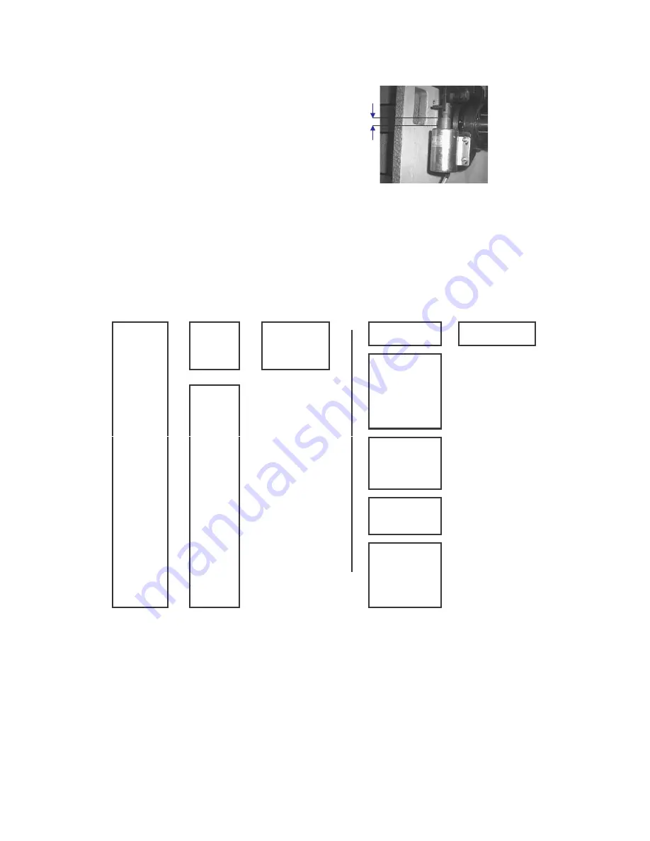
º Positioning of the Solenoid Bracket
Once a year remove the cap head screws from the
catch on the belt cover and open the cover.
Check that the clearance is correct as shown on the
photograph.
The clearance should be 6 - 7mm, if it varies from this
dimension adjust the bracket in the following manner:-
Loosen the two cap head screws holding the bracket
to the press casting and move the solenoid up or down
until the correct clearance is obtained.
Tighten the cap head screws on the retaining bracket,
close the belt cover and replace the socket screws in
the bracket.
Clearance
6 - 7mm
8. FAULT-FINDING
1.
The Ram moves 1
→
→
→
→
cycle (up and down)
→
→
→
→
OK
→
The Motor
→
→
→
→
Press the Foot-
→
→
→
→
runs
Switch once
1.
The connecting pin
is broken
2.
A solder joint on the
2.
The Ram does
foot-switch metal plug
1.
The Power Cord
→
→
→
→
not move
→
→
→
→
is bad
is disconnected
3.
The foot-switch cord
is damaged
2.
The power cord is
4.
The clutch spring
broken
has become slack
or has broken
3.
A solder joint on
5.
control box is faulty
the Power Cord
1.
A spring has become
→
→
→
→
metal plug is bad
slack
Press the
→
→
→
→
3.
The Ram ‘clunks’
2.
The clutch lever or
Power On
4.
The Thermal
several times
stopper is worn out
push-button
Trip is activated
3.
The solenoid is
defective
→
The Motor
5.
The Clutch is
4.
The control box is
does not run
engaged
defective
1.
The solenoid is
6.
Emergency Stop
4.
The Ram ‘clunks’
defective
switch is activated
→
→
→
→
many times
→
→
→
→
2.
A spring has become
slack
7.
Belt Cover is open
3.
The control box is
defective
1.
A stick roller is worn
2.
Grease is applied
5.
The Ram moves
incorrectly, or the
→
→
→
→
too slowly, or
→
→
→
→
wrong grease is
stops at Bottom
applied to the roller
Dead Centre
clutch
3.
The applicator is
seized