background image


(14)Y coordinate of the n-th cursor marker


(15) Header section ending data


(16)EOF


c) Data 

section 

Scan


test data is configured as a collection of 1-line data. 

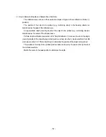
One-line data is fixed to a length of 769 bytes as follows: 
 

1 byte of  768 bytes of scan test data = 769 bytes 

 
The header represents line attributes in the following format: 


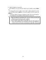
A0-Bit7(MSB) 0 
A0-Bit6 0 
A0-Bit5  1 when this line contains an antenna marker; 0 when it does not. 
A0-Bit4  1 when this line is specified as the surface wave; 0 when it is not 
A0-Bit3 0 
A0-Bit2 0 
A0-Bit1 0 
A0-Bit0(LSB) 0 


‑ 58 ‑


Содержание Handy Search NJJ-95B

Страница 1: ...Handy Search Instruction Manual...

Страница 2: ...reinforced concrete structures Before attempting to operate the NJJ 95B please read through this instruction manual carefully to learn all of its features and ensure correct and trouble free operatio...

Страница 3: ...operty damage is supposed to occur if this indication is neglected and this equipment is not operated correctly Examples of Pictorial Indication Electric shock The mark indicates CAUTION including DAN...

Страница 4: ...nology who shall coordinate this information with the Federal Government through the National Telecommunications and Information Administration The information provided by the UWB operator shall inclu...

Страница 5: ...ircumstances warrant The operation of UWB systems in emergency situations involving the safety of life or property may occur without coordination provided a notification procedure similar to that cont...

Страница 6: ...ock Do not connect disconnect the plug while your hands are wet Doing so could cause an electric shock Do not use place the NJJ 95B in a location where it is exposed to flammable or corrosive gas Doin...

Страница 7: ...wn Do not use place the NJJ 95B in a location where it is subject to vibration or shock Doing so may cause a personal injury or breakdown When loading unloading printing paper be careful not to cut or...

Страница 8: ...Appearance of the NJJ 95B vii...

Страница 9: ...n test screen example not during testing 16 2 3 Parameter Settings Screen 19 2 3 1 Display color 19 2 3 2 Inversion of the screen 20 2 3 3 Display mode 21 2 3 4 Gradation system 22 2 3 5 Calibration m...

Страница 10: ...splaying the thumbnail images of saved data 62 3 7 2 Reading saved data 62 3 7 3 Deleting saved data 63 3 7 4 Method for initialization of Compact Flash 65 3 8 Power off Procedure 67 3 9 Clearing up t...

Страница 11: ...After sales Service 88 8 Disposal 89 8 1 Disposal of Used Battery Pack 89 8 2 Disposal of the NJJ 95B 89 9 Specification 90 9 1 Handy Search NJJ 95B 90 9 2 Battery pack BP 3007 series 92 9 3 Charging...

Страница 12: ...wave from the concrete surface is automatically removed Thus only the reflected waves from rebar etc are shown Peak processing Image processing that shows only the waveform of the first peak on the s...

Страница 13: ...conditions of the object of investigation judging the search results with no consideration of the depth sensing capability may cause the accidental cutting of rebar 1 1 Function This radar has the fol...

Страница 14: ...1 For the case that the relative dielectric constant of concrete is a uniform 6 2 and the upper rebar has a diameter of 6 mm or more 2 The printer is optional 2...

Страница 15: ...l to the scanning direction transmit a smaller magnetic wave reflection Even if scanning is performed above rebar that is parallel to the scanning direction this device can still detect any rebar that...

Страница 16: ...ar can display scan results after changing sensitivity or performing image processing manual surface wave processing peak processing reproduction of original image fixed surface wave processing or ded...

Страница 17: ...so it is easy to operate 14 Operating with the battery pack and commercial power supply This radar can operate with the battery pack for about 1 5 hours at normal temperature It can also operate with...

Страница 18: ...DC10 NJJ 95B 1 License agreement for software DC20 NJJ 95B 1 Users Guide CD R H 7ZYMD0016 1 Options Table 1 2 shows optional products that are provided in addition to the standard components Table 1 2...

Страница 19: ...iagram Table 1 1 shows the total configuration of the Handy Search NJJ 95B Trans Rec antenna Receive Trans CompactFlash IrDA Trans Control section Opkey Distance Detector Memo CPU LCD Figure 1 1 Overa...

Страница 20: ...1 5 Configuration Figure 1 2 shows the external views of this radar Plan view drawing 149 216 Side view drawing 147 79 64 4 Fig 1 2 Handy Search NJJ 95B external dimensions diagram 8...

Страница 21: ...Rear view Units in trigonometry mm 9...

Страница 22: ...2 Parts Names and Functions 2 1 Handy Search NJJ 95B This section shows the operation panel of this unit and explains the functions for each group 1 2 3 4 5 6 7 8 9 10 11 12 13 Figure 2 1 Top View 10...

Страница 23: ...f image processing and various types of selection 6 PRCS Switch to image processing mode 7 None IrDAoptical receptor for communicating with the printer 8 None Compact flash memory card slot 9 START St...

Страница 24: ...8 14 15 Figure 2 2 Side View 16 17 14 18 Figure 2 3 Rear View 12...

Страница 25: ...Panel Number in Square Label Function 14 Mark indicating the scan test position 15 None Antenna face to radiate and receive electromagnetic waves 16 POWER ON OFF Turns power on and off 17 None Equipm...

Страница 26: ...External output display 9 Display range 5 Sensitivity display Fig 2 4 Scanning test screen example during scanning 1 Depth calibration value Displays the depth calibration value set at the parameter...

Страница 27: ...e section 3 2 4 Antenna Mark for how to use the antenna mark 7 Distance moved gauge Gauge for the distance moved while performing a scanning test 8 Battery capacity display Shows the general amount of...

Страница 28: ...7 Cursor Coordinates 2 Calibration method 1 Depth calibration value Displays the depth calibration value set at the parameter settings screen The method for setting the depth calibration value can be...

Страница 29: ...d is shown in X and depth in Y 8 Distance gauge Distance gauge in the direction the scanning was performed Displays the distance the main unit has moved 9 Battery capacity display Shows the general am...

Страница 30: ...13 Output data display Shows the output data destination set using the parameter settings screen See section 2 3 10 External Output for how to set up external output 18...

Страница 31: ...column Right column Display color Color Screen inversion Normal Display Mode B Level adjustment method Absolute value Measurement method Distance feed Depth calibration 06 2 3 Date 2006 07 21 18 09 Da...

Страница 32: ...from the set up items using the cursor keys invert display and switch to item selection using the cursor keys Select normal or inverted using the cursor keys or use the cursor keys to switch to item s...

Страница 33: ...e select display mode from the settings using the cursor keys inverting display and switch to item selection using the cursor key Select B or BA using the cursor keys or use the cursor keys to switch...

Страница 34: ...or keys Select absolute value or offset using the cursor keys or use the cursor keys to switch to item selection Figure 2 8Absolute Value Gradation Figure 2 9 Offset Gradation 2 3 5 Calibration method...

Страница 35: ...where the depth can be confirmed and the depth calibration value is unclear it is recommended to set the depth calibration to 08 0 0 In order to change the depth calibration value select Depth Calibra...

Страница 36: ...e set up items using the cursor keys invert display and switch to item selection using the cursor keys Set the distance error correction value using the cursor keys and use the cursor keys to switch t...

Страница 37: ...peration method 2 3 11 Display Range The display range is an item for setting the display limits of the scanning depth There are three settings deep standard and shallow Set the range of display based...

Страница 38: ...k to the standard settings In order to revert to standard settings select Return to Standard from the set up items using the cursor keys invert display and switch to item selection using the cursor ke...

Страница 39: ...ct flash memory The CF control screen is shown in Fig 2 10 3 Control items 2 Thumbnails 1 File selection Figure 2 10 CF Control Screen 1 File Selection The filenames for data saved on the compact flas...

Страница 40: ...e the battery pack Doing so could cause fire electric shock or breakdown Handy Search has a waterproof construction but must not be placed in water Do not expose the NJJ 95B to water or moisture and d...

Страница 41: ...isturbance of television pictures Doing so also adversely affects the depth sensing capability of the radar and may cause the cutting of reinforcing steel bars Do not use the NJJ 95B near a cell phone...

Страница 42: ...wer source battery pack This radar can be operated with the battery pack or 100 VAC power when an optional AC adapter is used Notes Use this radar in a place where the ambient temperature is 0 to 50 C...

Страница 43: ...down the rear of the battery pack to raise its front so it can be easily dismounted Figure 3 2 Mounting the battery pack Figure 3 3 Removing the battery pack Remarks When opening the battery cover ho...

Страница 44: ...igure 3 5 while the radar power switch is off Notes Mount remove the compact flash memory card while the power switch of this unit is off Make sure of the insertion direction before mounting the compa...

Страница 45: ...lash insert opening 2 If the eject switch is extended push in the switch Figure 3 4 Mounting the Compact Flash Memory Card Compact Flash Memory Card Compact flash 3 Insert the compact flash memory car...

Страница 46: ...lash out Compact flash 1 Open the lid of the 8 compact flash insert opening 2 Push the eject so that the eject button is pushed in 5 Push the eject button so that the eject button is pushed in 6 Close...

Страница 47: ...e orthogonal As necessary in order to perform a retest use and endpoint of the wall as a standard for the start line and scan test line A scan test applicable set up example is shown in Fig 3 6 1m Wal...

Страница 48: ...ed If the AC adapter is connected while operating using the battery the power turns off and then back on 3 2 2 Scan Test The scan test method is shown below a Place the 14 V on the side of the unit ov...

Страница 49: ...steel bars can be displayed by the method explained in section 3 2 5 Manual real time deduction processing or section 3 4 Image processing If the unit is moved too fast a buzzer will sound Data at the...

Страница 50: ...or the next scanning For the changing of sensitivity after scanning see Section 3 3 2 Sensitivity Switching 3 2 4 Antenna Mark If core boring or reinforced rebar locations are known beforehand shown o...

Страница 51: ...stopped However if the scan distance reaches 15m the buzzer sounds twice and the scan test automatically finishes 39...

Страница 52: ...14 V on the side of the unit over the start line and the forward backward 14 V over the scan test line b Press 9 START After about one second a short single buzzer sound is generated the fixed cursor...

Страница 53: ...y not be reproduced during scanning See section 3 4 Image Processing If scanning is to be performed again after scanning is complete using real time manual deduction processing automatic real time sur...

Страница 54: ...own in B mode maximum recordable scan test distance is 15 m The A mode waveform display portion in BA mode indicates the waveform at the vertical cursor position in BAmode Perform the following proced...

Страница 55: ...nsitivity set while scanning was stopped will be used for scanning 3 3 3 Cursor operation Figure 3 11 shows sample display with cursor operation 1 Cursor Display If the cursor keys are pushed after sc...

Страница 56: ...marks When switching from a scanning stopped state to scanning state all of the cursor marks are erased Cursorcoordinates Cursormarkcoordinates CursorMark Cursor Figure 3 11 Cursors and Cursor Marks 4...

Страница 57: ...g Peak processing Reproduction of original image Fixed surface wave processing Deduction processing 3 4 1 Manual surface wave processing Manual surface wave processing is used when the effect of refle...

Страница 58: ...processing and deduction processing image data will be displayed using manual surface wave processing that uses the surface wave at the cursor position indicated by of the last executed processing Man...

Страница 59: ...l surface wave processing including real time manual surface wave processing and deduction processing Procedure for reduction processing a a Press the 6 PRCS key Inverted display is shown as the item...

Страница 60: ...ves shaped as horizontal stripes appear near the surface of concrete after scanning with automatic real time surface wave processing performed the setting of Peak fixed may cause waves reflected by th...

Страница 61: ...t the bottom right hand side of the screen as the operation switches to image processing from the manual mode b Set Original image using the cursor keys Reproduction of original image will be performe...

Страница 62: ...Deduction processing eliminates reflected horizontal stripe waves from the screen after completion of scanning for extremely deep depths of 20 cm or more as shown in Figure 3 15A Procedure for reducti...

Страница 63: ...l deduction processing after scanning are not performed the image does not change when the cursor keys are used to set operation to deduction Deduction processing can be performed by moving the cursor...

Страница 64: ...t to be probed e g reinforcing steel is determined as the center of the reflected wave Perform depth calibration see section 3 2 6 Depth Calibration to reduce the error in the depth covering depth of...

Страница 65: ...s 200mm 200mm 200mm 60mm 120mm 180mm 240mm 10mm 300mm object to be probed n S position Vertical cross sectional drawing of Measurement directio tart 200mm 200mm 200mm 60mm 120mm 180mm 240mm 10mm 300mm...

Страница 66: ...er Set up the printer so that the IrDA optical receiver faces the IrDA optical receiver on the front of this unit at a distance of between 50 and 500 mm Note that if there is an obstacle between the r...

Страница 67: ...message Charge the printer s battery is displayed on the screen the voltage of the printer s battery pack has lowered When the message Charge the printer s battery is displayed on the screen the volta...

Страница 68: ...med using other equipment NJJ 95B PC etc the compact flash may not be recognized Please do not use a compact flash memory that was used with a NJJ 95A As the data format used by NJJ 95Aand NJJ 95B are...

Страница 69: ...11 MarkX 1 3 0x0D 0x0A 12 MarkY 1 14 0x0D 0x0A 13 MarkX n 2997 0x0D 0x0A 14 MarkY n 508 0x0D 0x0A 15 END 0x0D 0x0A 16 0x1A 0x0D 0x0A Items in the header section 1 ID data such as the model name 2 Dat...

Страница 70: ...xed to a length of 769 bytes as follows 1 byte of header 768 bytes of scan test data 769 bytes The header represents line attributes in the following format A0 Bit7 MSB 0 A0 Bit6 0 A0 Bit5 1 when this...

Страница 71: ...umber of measurement lines 1 2 Text mode a Configuration The data format of the text mode is the same as for the binary mode The difference from the binary mode is that the text mode processes all dat...

Страница 72: ...screen data from scan testing can be saved to a compact flash memory card The file name of saved data is determined as follows B 1 2 3 0 4 5 0 0 0 1 Data No Scan test time The first 2 digits indicate...

Страница 73: ...Display of thumbnails Figure 3 17 CF Control Screen 61...

Страница 74: ...for Display color on the setting screen the thumbnail image display will also be monochrome 3 7 2 Reading saved data To open data that has been saved select the file to be opened using the cursor keys...

Страница 75: ...and press the ENTER key When the message Do you want to delete the data Yes No is displayed select Yes using the cursor keys and press the ENTER key See Figure 3 19 Select Yes using key and push the...

Страница 76: ...To delete the data select Yes and Select Delete and press the ENTER key press the ENTER key Figure 3 19 Deleting Saved Data 64...

Страница 77: ...started After the message disappears the compact flash memory is initialized and all data is deleted See Figure 3 20 Notes Never remove insert the compact flash memory card or turn off the power swit...

Страница 78: ...ess the ENTER key to start initialization Select Yes Message indicating compact flash After initialization all data is erased memory is being initialized Figure 3 20 Initializing Compact Flash Memory...

Страница 79: ...he compact flash memory is deleted when the power is turned off 3 9 Clearing up the radar and accessories Turn off the power disconnect all cables the radar and put them together with the radar into t...

Страница 80: ...e NJJ 95B immediately when a possible malfunction is detected and follow only the detailed procedure in this instruction manual If it cannot be restored to normal operation contact our nearest branch...

Страница 81: ...apacity The battery availability indicator is displayed at the upper right of the LCD screen of this radar When the battery availability indicator shows the 0 state see Fig 3 21 and the buzzer sounds...

Страница 82: ...ry pack s operating time is shortened in a cold region The battery pack does not need to be discharged or used up before it is charged It is considered that the battery pack has reached its service li...

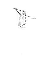
Страница 83: ...B Terminals ACharge confirmation mark Figure 3 22 Battery Pack 71...

Страница 84: ...f charging When the CHARGE lamp goes off the battery pack has been charged enough for practical use The battery pack will be fully charged if it is charged for another hour continuously after the lamp...

Страница 85: ...Shutter Charge lamp Figure 3 23 Battery Charger 73...

Страница 86: ...wn Stop using the NJJ 95B immediately when a sign of malfunctioning is detected and follow only the detailed procedure in this instruction manual If it cannot be restored to normal operation contact o...

Страница 87: ...r instruction manual to use the printer correctly and safely Remarks See Section 3 6 External Output Methods regarding Handy Search settings For details on printer handling see the printer instruction...

Страница 88: ...cover is closed paper is ejected from the top of the printer Thermal head Records data on paper Be careful that the thermal head is hot immediately after printing Platen cover The thermal head is rele...

Страница 89: ...cting terminals and push the battery pack in the direction indicated by the arrow 2 Removing the battery pack See Figure 4 2 B a Turn the printer power switch OFF b Slide the battery pack in the direc...

Страница 90: ...completed when a click sound is heard Arrow 2 in Figure 4 3A 2 Turn ON the printer power switch 3 Place the printer upside down and slide the paper cover in the direction indicated by the arrow while...

Страница 91: ...en the paper cover Then simply lift the paper roll to remove Insert the end of paper straight into the paper insertion port Diagonal insertion may cause a paper feed failure 5 Method for removing the...

Страница 92: ...d on the liquid crystal display in addition to the message Printing Remarks See Section 3 6 External Output Methods regarding Handy Search settings For details on printer handling see the printer inst...

Страница 93: ...2 Connecting theAC adapter 1 Confirm that the power switch on the main unit is set to OFF 2 Connect theAC cable to theAC power connector on theAC adapter See Figure 4 5 1 3 Connect the DC jack of the...

Страница 94: ...reflecting objects can be calculated from the time the reflected waves need to reach the receiving antenna The horizontal locations of the objects can be detected by moving the main unit on the surfa...

Страница 95: ...of the rebar is at least 6mm Objects to be probed that are at a depth of less than 75 mm have an interval spacing of at least 75 mm and where the depth of the object to be probed is greater than 75 m...

Страница 96: ...Concrete Rebar D 75mm L 75mm D 75mm Difficult to implement 84...

Страница 97: ...e fire or breakdown Should the NJJ 95B emit an abnormal sound odor or smoke immediately turn off the power switch remove the battery pack disconnect the power plug from the socket outlet and contact o...

Страница 98: ...AC adapter according to according to section 3 1 Preparations for Scanning and operate the radar with the battery pack The battery pack is exhausted rapidly Check if the battery pack is charged suffi...

Страница 99: ...rding to the printer instruction manual CF Not Available message appears if the CF key is pushed Has the compact flash card been removed Was the compact flash card inserted after turning the power on...

Страница 100: ...our nearest branch office sales outlet or service station Information to be reported Product name model number and serial number Detailed information about the abnormal state Company organization nam...

Страница 101: ...ited 8 1 Disposal of Used Battery Pack Discharge the used battery pack lithium ion battery completely insulate the charging terminals by taping or the like and then dispose of it as nonflammable refus...

Страница 102: ...ess than 75 mm at least 75 mm Objects to be probed are at a depth of 75 mm or more Interval greater than depth thereof 15m B mode vertical cross section BAmode vertical cross section and reflected wav...

Страница 103: ...Dimensions Weight About 149 W x 147 H x 216 D mm Approximately 1 1kg 91...

Страница 104: ...hen discharging Dimensions Weight Lithium ion battery 1500 mAh 7 2 V 0 40 C 10 60 C About 38 x 70 x 20mm Approximately 103g 9 3 Charging Device BC 3008 series Item Specifications Power supply Output v...

Страница 105: ...below for the nearest branch office sales outlet or service station JapanRadioCo Ltd Section I International Business Department Sales and Marketing 1 1 Shimorenjaku 5 Chome Mitaka shi Tokyo 181 8510...

Отзывы: