19 | Operation
2 Operation
I Operating the Rudder Feedback Unit
The Rudder Feedback Unit can be used in a rudder angle indicator system and as a part of the control loop in a steering
control system. The output can be connected to an Analog Interface Mk.2. There are two types of rudder feedback units
available: Rudder Feedback Unit MD and Rudder Feedback Unit HD.
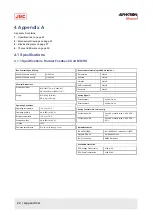
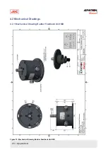
The Rudder Feedback Unit MD is medium in size. It is equipped with a dual potentiometer (2 x
2KΩ)
which can transfer
the rudder angle to 2 different systems. There are no limit witches present in the Rudder Feedback Unit MD.
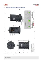
The Rudder Feedback Unit HD is larger in size. It is equipped with a dual potentiometer (2 x
2KΩ)
which can transfer the
rudder angle to 2 different systems. The Rudder Feedback Unit HD has two sets of limit switches.
There are two types of transmissions to choose from:
•
RFU Linkage Transmission
•
RFU Chain Transmission
The Rudder Feedback Unit MD and the Rudder Feedback Unit HD can each be equipped with either the RFU Chain
Transmission or the RFU Linkage Transmission.
Limit Switches
The Rudder Feedback Unit HD is equipped with limit switches. There are two sets of limit switches; two for port side and
two for starboard. The function of the limit switch is to open its contact once a certain position on the rudder feedback
axle is reached. Utilizing this contact signal from the limit switch, the limit switch can be used to prevent the rudder from
moving further than a predefined angle or to indicate that the rudder has reached its maximum position.
Note The limit switches need to be physically set. Each limit switch has an adjustment screw by which the limit
switch can be set. The adjustment screw can easily be operated when the hatch of the RFU HD is removed.
Note The limit switch itself does not start or stop the rudder. The limit switch simply opens its contact at
certain angle of the rudder feedback axle. It is up to third party systems to use the contact of the limit switch for
controlling the rudder.
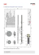
RFU Chain Transmission
The principle of the RFU Chain Transmission is quite straight forward. The Rudder Feedback Unit and the rudder are
connected via a chain. The movement (turning) of the rudder is transferred to the Rudder Feedback Unit via the chain.
The potentiometer of the Rudder Feedback Unit translates that movement into a potentiometer output signal. It is up
to other systems to pick up the signal from the Rudder Feedback Unit and translate it in readable values for ship’s
personnel.
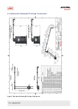
RFU Linkage Transmission
The principle of the RFU Linkage Transmission is that the Rudder Feedback Unit and the rudder itself are connected
via a linkage system. The movement (turning) of the rudder is transferred to the Rudder Feedback Unit via the linkage
system. At the Rudder Feedback Unit, the linkage system will turn the axle of the Rudder Feedback Unit. And so, when
the axle of the Rudder Feedback Unit turns, the output of the potentiometer will change, and with that, the reading of
the rudder angle. Depending on how the limit switches are set, turning the axle the limit switches will in turn open their
contacts.
Important Notes
Any dead-band setting regarding the Rudder Feedback Unit needs to be set in the device that receives the potentiometer
signals from the Rudder Feedback Unit. Dead-band settings cannot be made in the Rudder Feedback Unit itself.
As long as all parts of the Rudder Feedback Unit are functioning properly, no calibration of the Rudder Feedback Unit, or
any of its parts, is needed. If any of the rudder readings are off and the potentiometer signal from the Rudder Feedback
Unit is OK, then calibration of the rudder readings needs to be done in the device that receives the potentiometer signals
from the Rudder Feedback Unit.
•
WARNING
•
The axle of the Rudder Feedback Unit has to be zeroed before the rudder feedback unit can be operated.
Damage to the rudder feedback unit, or any of its components, can occur when the axle is not properly

