


17 | Installation Instructions
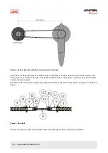
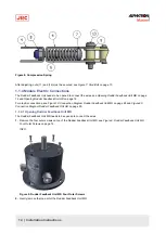
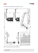
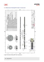
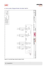
Figure 13: Rudder Feedback Unit HD Electric Connections
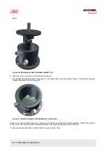
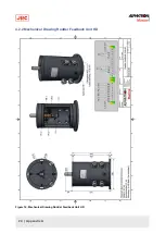
When the connections have been made, close the front hatch of the Rudder Feedback Unit HD. When replacing the
screws, first apply the middle top and the middle bottom screw of the hatch and torque to 6,5 Nm.
After this, all other screws can be replaced and torqued to 6,5 Nm.
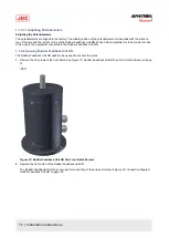
1.1.4.2.1 Adjusting Limit Switches and Potentiometers
Adjusting the Limit Switches
When adjustment of the limit switches of the Rudder Feedback Unit HD is needed, use an Allen key to loosen the
corresponding cam and adjust it.
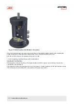
After adjustment, tighten the screw again to secure it. See Figure 14: Rudder Feedback Unit HD Limit Switches on page
18 for information on which limit switch is connected to which system and direction.


