


18 | Installation Instructions
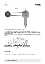
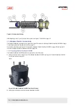
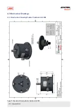
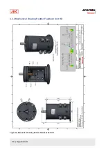
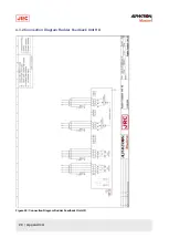
Figure 14: Rudder Feedback Unit HD Limit Switches
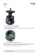
Adjusting the Potentiometers
The potentiometers are aligned in the factory. The middle position of the potentiometers corresponds with the mark on
top of the axle and the red dot on top of the Rudder Feedback Unit HD. When further adjustment is to be made, this has
to be done in the equipment connected to the Rudder Feedback Unit HD.
1.1.5 Cable
Use the following connection cables:
Name
Specification
Shield (Y/N)
Norm
Potentiometer signal
3 x 1.5 mm
2
Y
Limit switches
4 x 1.5 mm
2
Y
Table 3: Connection Cables
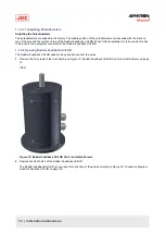
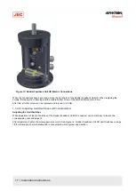
1.1.6 Grounding Modules
To function properly, the Rudder Feedback Unit must be grounded to the ship’s mass.
For this purpose, the Rudder Feedback Unit has a grounding bolt. Connect the grounding bolt to the ship’s mass with a
low impedance connection.


