


31 | Interfaces
The cable lengths in Table 2 are calculated and corrected by reducing the input voltage by 10% (10.8
Vdc and 21.6 Vdc) to compensate for variation in the power source. The total DC resistance for the
two cables shown in Table 3.
Cable Type
Inner Conductor DC
Resistance [Ω/km]
Outer Conductor DC
Re
sistance [Ω/km]
Total DC Resistance
[Ω /km]
RG58
24.9
15.8
40.7
RG214
4.5
6.5
11
Table 3: Total DC resistance (cable examples)
NOTICE
If using a coaxial cable that is different to what is specified in this section (RG58 and
RG214), then verify that the coaxial cable maximum signal loss (listed in Table 1 on
page 29) is respected and calculate the maximum cable length as a function of the
input voltage and the total DC resistance. Contact Alphatron Marine to get
assistance on selection and acceptance of a specific coaxial cable.
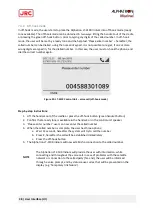
NOTE
The LT-3110 Control Unit must be powered off when connecting or disconnecting
the LT- 3130 Antenna Unit.
Содержание Alphatron LT-3100 Iridium
Страница 1: ...Alphatron LT 3100 Iridium Installation Operation Manual www alphatronmarine com ...
Страница 44: ...44 Appendices Appendices ...
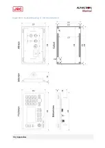
Страница 46: ...46 Appendices Appendix B Outline Drawing LT 3110 Control Unit ...
Страница 47: ...47 Appendices Appendix C Outline Drawing LT 3130 Antenna Unit ...
Страница 50: ...50 Appendices Appendix F Outline Drawing LT 3120 Handset ...
Страница 51: ...51 Appendices Appendix G Outline Drawing LT 3121 Cradle ...


