


30 | Interfaces
where U is the control unit input voltage [V], P
D
is the antenna unit power (10 W), and RCable is the
total DC
resistance [ꭥ/km] (sum of inner and outer conductor resistance).
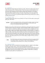
Figure 18: Coaxial Cable Total DC Resistance vs. Cable Length (12 Vdc and 24 Vdc)
In Figure 18 two different input voltages (12 Vdc and 24 Vdc) illustrate the maximum length of the
coaxial cable as a function of the DC cable resistance.
NOTE
The DC cable resistance that is illustrated in Figure 22 and used to calculate the
maximum cable length is the sum of the DC inner conductor resistance and the DC
outer conductor resistance. Some data sheets are not providing sufficient
information about the DC resistance, in which cases, the cable manufacture must be
approached to obtain this information.
Table 2 lists two coaxial cables and their maximum allowed cable lengths.
Coaxial cable
12 Vdc Supply Max Cable
Length
24 Vdc Supply Max Cable
Length
RG58
70 m
285 m
RG214
265 m
500 m
Table 2: Maximum coaxial cable length to be used on 12 Vdc and 24 Vdc (cable examples)
Содержание Alphatron LT-3100 Iridium
Страница 1: ...Alphatron LT 3100 Iridium Installation Operation Manual www alphatronmarine com ...
Страница 44: ...44 Appendices Appendices ...
Страница 46: ...46 Appendices Appendix B Outline Drawing LT 3110 Control Unit ...
Страница 47: ...47 Appendices Appendix C Outline Drawing LT 3130 Antenna Unit ...
Страница 50: ...50 Appendices Appendix F Outline Drawing LT 3120 Handset ...
Страница 51: ...51 Appendices Appendix G Outline Drawing LT 3121 Cradle ...


