58
ᴾ
▋
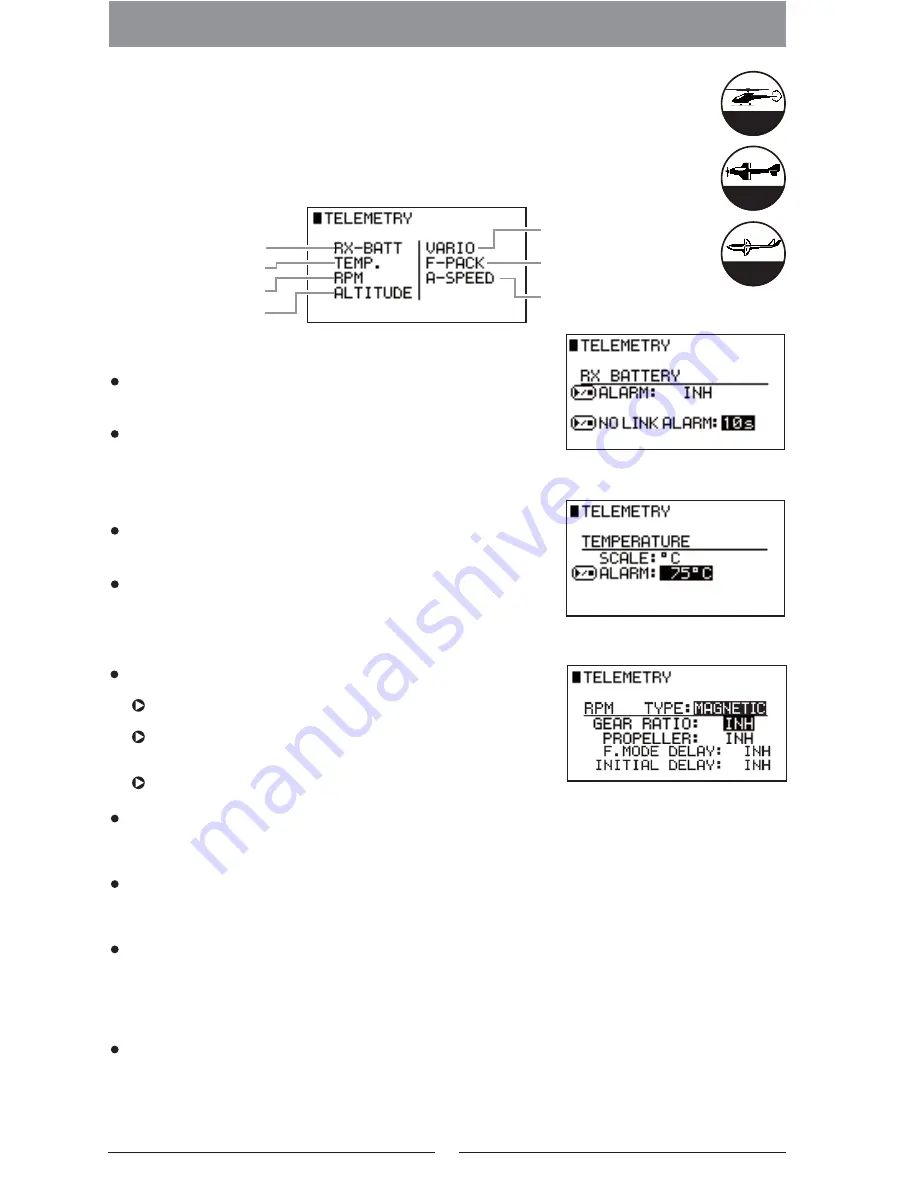
Telemetry System【TELEMETRY】
▋
Function Explanation
This allows optional telemetry sensors present in a particular aircraft, gathering information
such as Receiver Voltage, Altitude, Temperature or Propeller or rotor blade r.p.m., etc.
In addition to the data on the display, alarms are used, so as aircraft conditions can be
monitored without taking your eyes off the aircraft.
▋
Setting
Method
▋
Receiver battery (RX-BATT)
No Link Alarm (NO LINK ALARM)
Receiver Battery Alarm
This function alerts to a drop in receiver battery voltage. Initially it is inhibited.
To activate, set the alarm Voltage between 3.0V ‒9.0V in 0.1V increments.
No Link Alarm
This will warn when the transmitter is no longer receiving data
from the model. Initially it is set as inhibited. Set the delay after which the alarm should sound to either 10S (10
seconds), 15S (15 seconds), 20S (20 seconds), or 30s (30 seconds).
▋
Temperature (TEMPERATURE)
Units (SCALE)
This selects the units for temperature display - Celcius ( °C) or
Fahrenheit (°F). Select the units as desired.
Alarm (ALARM)
This sets the temperature at which the alarm will sound ‒
between 30 and 500 °C. Initially this alarm is inhibited. Set the
temperature to the desired alarm point.
▋
Revolutions Per Minute (RPM)
Gear Ratio (GEAR RATIO)
Number of Blades (PROPELLER)
Delay (F.MODE DELAY)
It is possible to display and store the maximum r.p.m. recorded in each flight mode. However, when the flight
mode is changed, the sensor may immediately store a maximum value, which would be invalid. To avoid storing
incorrect r.p.m. data, this function allows rpm to stabilize before storing any data. Initially it is set to inhibited. Set
the desired numerical amount which would suit with your model. The delay can be set from 0.5s (0.5 seconds) ~
10.0s (10 seconds) in 0.5 seconds increments.
Helicopter
Airplane
Glider
System List
Initial Delay (INITIAL DELAY)
In order to detect the Signal Pulse from the Brushless motor, it is essential to use ESC, however, certain ESC on
the R/C market offers the function to alert initial start with sound of beep. This canbe recognised as a highest
RPM signal on this sensor, So False RPM may appear on the data screen. In order to avoid this false signal
reading, It is capable to set the transmitter to read the signal with some delay between 5seconds to 30seconds
(with 5seconds interval. Initially it is set as INH. Set the required timing by seconds to activate this function.
Sensor type
Select the Rotation Sensor type depending on usage.
Magnetic Sensor (MAGNETIC)
By using the Magnet on Rotation object to sense the rotation.
Optical Sensor (OPTICAL)
By using the optical sensor which detect the obstruction of the
light per propeller blade.
Motor Pulse Sensor (MOTOR)
By detecting the Pulse signal on the brushless motor to sense the rotation.
It is possible to monitor the Helicopter's actual rotor blade r.p.m. by entering the gear ratio. Check the gear ratio
for each Helicopter by checking your manual. Initially it is set as inhibited. Set the necessary numerical value.
Gear Ratios can be set between 1.00 ~20.00 in 0.01 increments.
It is possible to monitor an Airplane's actual Propeller r.p.m by installation of an optical sensor. It is necessary to
input the number of blades of the propeller in order to have actual Propeller r.p.m displayed. Initially, it is
inhibited. The number of Propeller blades can be set between 1-20.
Receiver Battery Voltage
Temperature
Variometer
Air speed
Motive Power Battery
(Voltage/Capacity)
Rotation Speed
Altitude
Содержание C.O.L.T.
Страница 1: ...Classic Old Looking Transmitter...
Страница 82: ...http www jrpropo co jp...


