17
130112_Rev 2 GF 160 DV 2/22
8. Gas Supply Connection
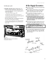
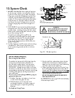
Route the gas supply line to the flex line behind the Utility
Cover at the rear leg.
The gas supply line should be 3/8” npt with a 1/2” diameter
supply, or the appropriate size to provide sufficient gas
pressure to the valve regardless of the input setting.
The use of Flexible Gas Appliance Connectors is
acceptable in many areas in the U.S. However, Canadian
methods vary depending on local code.
ALL INSTALLATIONS MUST COMPLY WITH LOCAL
CODE OR IN THE ABSENCE OF LOCAL CODE,
MUST COMPLY WITH THE MOST RECENT EDITION
OF THE NATIONAL FUEL GAS CODE ANSI Z223.1/
NFPA 54 OR CAN-B149.
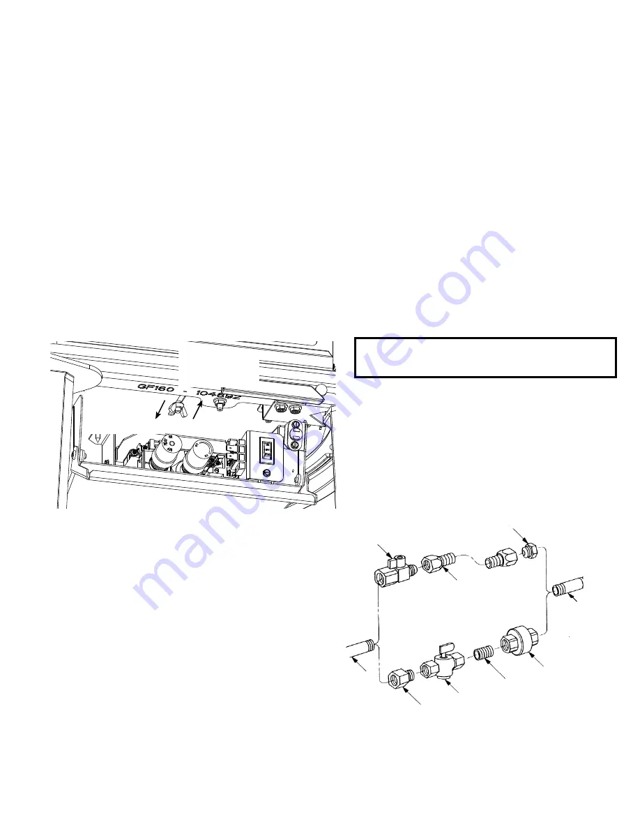
All codes require a gas shut-off valve (gas cock) and union,
to be installed in the supply line, and in the same room as
the appliance. This allows for the disconnection of the stove
for servicing and maintenance. See fig.
8.1.
A T-HANDLE GAS COCK IS REQUIRED IN
MASSACHUSETTS TO COMPLY WITH CODE
248CMR.
Secure all joints tightly using appropriate tools and sealing
compounds.
For propane units be sure to use compounds
that are propane resistant.
Turn on gas supply and test for
gas leaks at all joints.
Figure 8.1. Gas supply line connection alternatives.
Fuel Conversion, cont’d.
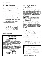
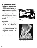
16. NATURAL GAS ONLY: Adjust the Air Shutter. Fig.
7. 10
The factory setting for NG is 1/16” open. Adjustment may be
necessary to provide the best flame picture depending upon the
specific vent configuration.
• Start with the shutter set open to 1/16”.
• Push the shutter stem back (to the rear) to restrict air.
• Pull the shutter stem forward (toward yourself) to open the
shutter and add oxygen to the fuel mix.
With some experimentation, you will find the shutter position
that works best for that particular installation.
• Run the stove at least 15 minutes to let the burner settle-in
before making further adjustments in very small increments
(1/16” - 1/8”)
Figure 7.10.
Pull the shutter forward to increase primary air.
Push it back to restrict air.
CLOSE -
Restrict oxygen
OPEN -
Increase oxygen


