14
130112_Rev 2 GF 160 DV 1/22
Tools required:
• 1/2” or 13 mm wrench or deep-well socket,
• Torx T20 screw driver
• 1/4” socket driver or spade screwdriver
• 7/16” open-end wrench
• Small pliers or vice-grip
Conversion Kit Contents:
• 1, regulator tower labeled LP
• LP orifice: 1.45 mm
• 1, Pilot Injector
- #51 NG - 129472
#30 for LPG - 129473
• #8 x 1/2” sheet metal screw
• Label A - to be completed and applied to
the lower door hinge.
• Label B - apply to the stove’s Rating Plate
• Small valve label - apply to valve body
• 4mm Hex Key
• Instructions
7. Fuel Conversion
The GF 160 DV gas stove is shipped from the factory equipped
to burn NATURAL GAS only. If PROPANE gas is to be used as
fuel, the appliance must first be converted by using the Propane
Conversion Kit 158295 included with the stove. Use Natural Gas
Conversion Kit 158293 to revert back to Natural gas.
WARNING:
THE CONVERSION KIT IS TO BE
INSTALLED BY AN AUTHORIZED SERVICE
TECHNICIAN IN ACCORDANCE WITH THE
MANUFACTURER’S INSTRUCTION AND
ALL CODES AND REQUIREMENTS OF
THE AUTHORITY HAVING JURISDICTION.
FAILURE TO FOLLOW THESE INSTRUCTIONS
COULD RESULT IN SERIOUS INJURY OR
PROPERTY DAMAGE. THE QUALIFIED
AGENCY PERFORMING THIS WORK
ASSUMES RESPONSIBILITY FOR THIS
CONVERSION.
IN CANADA:
THE CONVERSION SHALL BE CARRIED
OUT IN ACCORDANCE WITH THE
REQUIREMENTS OF THE PROVINCIAL
AUTHORITIES HAVING JURISDICTION
AND IN ACCORDANCE WITH THE
REQUIREMENTS OF THE CAN1-B149.1 AND .2
INSTALLATION CODE.
Fuel Conversion Procedure
1. Turn off gas supply
to stove.
2. Open the door and release the glass frame latches
to remove
the glass frame and open the firebox. Tilt the glass frame
forward and lift it out of the stove. See fig. 2.1, page 5.
3. Open the Controls compartment under the firebox.
Loosen
the Air Shutter wing nut
located below the firebox floor and
push the stem back far as it will travel. See fig. 7.1.
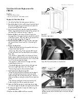
4. Remove the Burner:
Lift the front of the burner base to
disengage it from the support brackets and pull it forward off
of the burner injector. Then tilt it side-to-side and pull it out
through the door opening. Fig. 7.2.
5. Change the Burner Injector.
See fig. 7.3. Using a 1/2” open end wrench or deep-well
socket, remove the burner injector from the orifice holder and
replace it with the injector supplied in the conversion kit.
CAUTION: Do NOT over tighten the Burner Injector. Over
tightening can damage the brass elbow and cause a gas leak!
6. PROPANE ONLY: Install the 1/2” Air Shutter Lock Screw
(Fig. 7.3)
provided in the LP Conversion Kit. The screw
automatically sets the new, minimal shutter opening.
7. Change the Pilot Injector,
Fig 7.3.
• Use a 1/4” nut driver to remove the sheet metal screws and
Pilot Shield from the pilot assembly.
• Change the Pilot Orifice. Pull the Pilot Hood off of its base.
It will snap by the retainer clip shown in Fig. 7.3.
• Use a 4mm Hex Key to remove the pilot injector from pilot
base and replace with the one in the fuel conversion kit.
• Replace the pilot hood by simply pushing it back into place
on its base. Replace the pilot shield.
8. Baffle Conversion - PROPANE ONLY:
•
Remove two, 10 mm nuts to detach and drop the Exhaust
Baffle. You do not need to remove it from the firebox. See
Fig. 7.4.
• Loosen two, 10 mm nuts on the Upper Baffle,
(Figs. 7.4 and 7.4a), enough to break both end wings off at
the perforations. Retighten the two nuts.
• Replace the Lower Baffle.
9. Replace the Burner.
Tilt the burner assembly downward
to engage the venturi tube with air shutter assembly.
BE
CERTAIN THE BURNER IS LEVEL AND SECURELY
ENGAGED WITH THE FRONT SUPPORTS ON THE
FIREBOX FLOOR.
10. Regulator Conversion. Fig. 7.5.
• Using a Torx T-20 screwdriver, remove the mounting
screws from the original regulator and remove that assembly.
• Install the conversion regulator motor using the new
components included from that kit.


