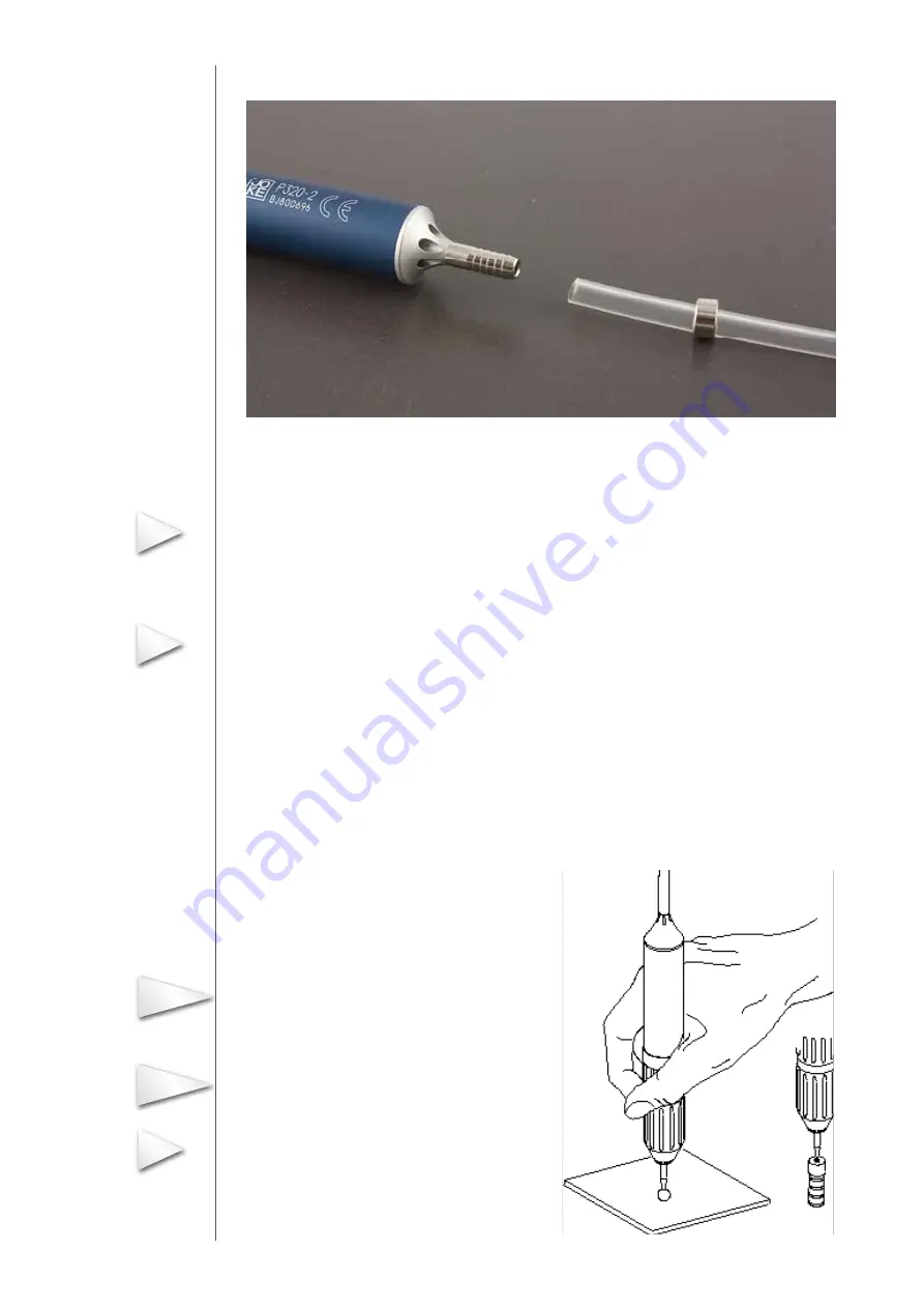
Push-fit the other end with the locking ring on to the connection on the handpiece (Fig. 7.3)
Fig. 7.3 Connecting the hose to the handpiece P 320-2
By briefly pulling rearwards, the hose is firmly anchored by the locking ring against disconnection.
The handpiece locking ring is enclosed in the packaging.
Performing a test run
The pressure controller is set to zero at the factory. Once the air supply has been connected, slow-
ly turn the knob clockwise in order to maintain a pressure of 0.2 MPa.
1. Firmly push the test mandrel for the test run into the handpiece receptacle
2. Pull up and turn the controller knob to unlock. After adjusting the nominal value, depress the
knob again to lock.
3. Operate the foot switch to switch the handpiece on and off and in order to check perfect opera-
tion.
Refer to section 8 in case of malfunctions.
Using the handpiece P 320-2 for the first time
7.4 (symbolic drawing)
1. Firmly push the selected tool into the handpiece
receptacle (Fig. 7.4).
Only use an approved tool with a shaft dimension of
ø 1.6 mm according to the joke catalogue!
Press the tool on to a firm base while doing so.
With a sharp tool, use the auxiliary tool for holding.
2. Operate the foot switch to switch the handpiece on and off.
Adjust the tool speed if necessary by regulating the air
pressure at the rotary knob on the pressure reducer.
09
Info
Info
Important
Caution
Info


