Operation
Device setup and connection
1. Set up the maintenance unit or secure it to the wall or workbench.
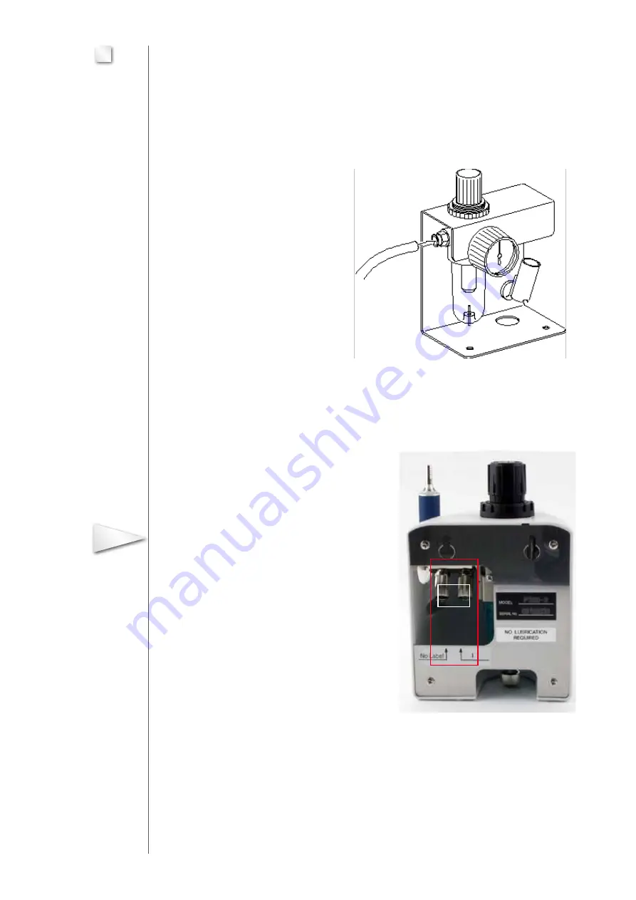
2. Push-fit the hose for external air supply on to the maintenance unit. By briefly pulling rear-
wards, the hose is safeguarded against disconnection (Fig. 7.1).
Fig. 7.1 (symbolic drawing)
3. After installing the hose coupling, connect the other end of this hose to an external com-
pressed-air hose.
4. Connect the two hoses of the foot switch to
the connections (A) of the maintenance unit (Fig. 7.2).
Unscrew the union nuts and push on to the
hose. Push-fit the hose ends on to the
connections before retightening the union nuts.
In doing so, take care that the hose marked
number 1 is located on the likewise numbered
connection piece (1).
Fig. 7.2 Rear view
5. Plug the hose for the handpiece on to the maintenance unit and secure by
pulling rearwards. Push the locking ring (Fig. 7.2/10) on to the hose beforehand.
08
7
Important
A


