


28
RW SERIES REVERSIBLE CHILLER INSTALLATION MANUAL
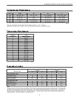
HE
GPM x 500*
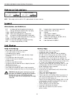
Legend
Abbreviations and Definitions
Reference Calculations
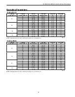
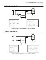
Heating Calculations:
Cooling Calculations:
LWT = EWT +
HR
GPM x 500*
LWT = EWT -
NOTE:
* When using water. Use 485 for 15% methanol/water or Environol solution.
ELT
= entering load fluid temperature to heat pump
EER
= cooling energy effciency (TC/KW)
LLT
= leaving load fluid temperature from heat pump
PSI
= pressure drop in pounds per square inch
LGPM = load flow in gallons per minute
FT HD = pressure drop in feet of head
LWPD = load heat exchanger water pressure drop
KW =
kilowatt
EST
= entering source fluid temperature to heat pump
HR
= heat rejected in MBTUH
LST
= leaving source fluid temperature from heat pump
TC
= total cooling capacity in MBTUH
SGPM = source flow in gallons per minute
COP
= coefficient of performance (HC/KW x 3.413)
SWPD = source heat exchanger water pressure drop
HC
= heating capacity in MBTUH
HE
= heat of extraction in MBTUH
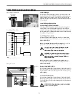
Verify the following:
• High voltage is correct and matches nameplate
• Fuses, breakers and wire size are correct
• Low voltage wiring is complete
• Piping is complete and the water system has been cleaned
and flushed
• Air is purged from closed loop system
• Isolation valves are open and water control valves or loop
pumps are wired
• Service/access panels are in place
• Transformer has been switched to lower voltage tap if needed
(208/230 volt units only)
• Unit controls are in “off” position
• Flow switches are installed and ready or wires are jumpered
• Freeze detection setpoints have been set in the microprocessor
WARNING: Verify ALL water controls are open and
allow water flow PRIOR to engaging the compressor.
Failure to do so can result in freezing the heat
exchanger or water lines causing permanent damage
to the unit.
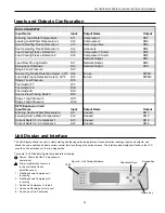
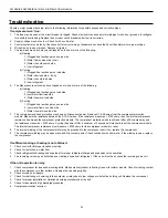
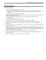
Unit Startup
Startup Steps
• Set aquastat control above cooling setpoint.
• Set aquastat control in cooling mode.
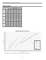
• Slowly reduce the control setting until both the compressor
and water control valve/loop pumps are activated. Verify that
the compressor is on and that the water flow rate is correct
by measuring pressure drop through the heat exchanger and
comparing to the Pressure Drop table (page 32). Check for correct
rotation of scroll compressors. Switch any two power leads at the
L1, L2, and L3 line voltage termination block if incorrect.
• Perform a cooling capacity test by multiplying GPM x
∆
T x 485
(antifreeze/water). Use 500 for 100% water. Check capacity
against catalog data at same conditions.
• Set control to “OFF” position.
• Leave unit “OFF” for approximately five (5) minutes to allow
pressure to equalize.
• Adjust control below heating setpoint.
• Set control in “HEAT” position mode.
• Slowly increase the control setting until both compressor and
water control valve/loop pumps are activated. The reversing
valve should be heard changing over.
• Perform a heating capacity test by multiplying GPM x
∆
T x 485
(antifreeze/water). Use 500 for 100% water. Check capacity
against catalog data at same conditions.
• Check for vibrations, noise and water leaks.
• Set system to maintain desired setpoint.
• Instruct the owner/operator of correct control and
system operation.
Содержание RW Series
Страница 39: ...THIS PAGE INTENTIONALLY LEFT BLANK ...