


19
RW SERIES REVERSIBLE CHILLER INSTALLATION MANUAL
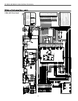
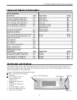
TB
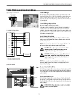
Typical AquaStat
24VAC
24V COM
Comp 1
Comp 2
Rev Valve
Acc 2
Acc 1
Alarm
Circuit 1 Alarm
Circuit 2 Alarm
24VAC
24V COM
Comp 1
Comp 2
Rev Valve
Accessory Item 1
R
C
Y1
Y2
O/B
X2
X1
L
LC1
LC2
R
C
Y1
Y2
B
NOTES:
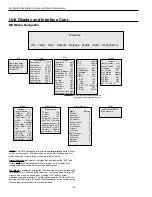
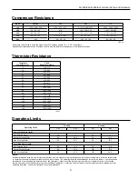
1) Acc Output 1 is cycled with the lead compressor
2) Acc Output 2 is cycled with the lag compressor
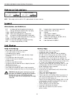
Unit Power Supply
208-230/60/3,
460/60/3, or 575/60/3
G
L3
L1
L2
PB
Black
Red
White
Black
White
Red
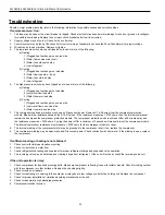
Field Wiring and Control Setup
High Voltage Connections
Low Voltage Connections
Line Voltage
Power supply wiring connects directly to lugs on the topo of the
electrical disconnect. In 208-230V applications, heat pumps are
factory wired for 208V supply. In the case of 230V supply, the
blue and red wires from the primary of the transformer will need
to be swapped.
Low Voltage Operation
Thermostat/Controller (Aquastat)
A two-stage 24VAC aquastat or liquid controller (field supplied)
must be used to turn the reversible chiller on/off, and to switch
modes for heating/cooling. Multiple chillers in the same bank must
be controlled from one aquastat/controller (must be isolation relays
for multiple unit applications).
Low Voltage Connections
Connect low voltage wiring as shown in Figure 9. Connections
shown are for typical aquastat. Actual connections may vary with
specific device used.
NOTE:
If a separate transformer is used to supply a Y1, Y2, or B
signal to the unit controls, isolation relays must be used.
CAUTION: Use only copper conductors for field
installed wiring. Terminals in the unit are not
designed for other types of conductors.
WARNING: All wiring must comply with local and
state codes. Disconnect the power supply before
beginning to wire to prevent electrical shock or
equipment damage.
NOTE:
Accessory 1 output is selectable as normally open or
normally closed using the unit display. Normally closed is the
factory default setting.
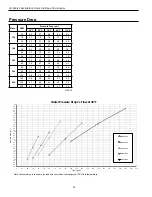
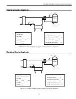
Source Flow Switch (SFS)
Unit is factory shipped with no connections on Flow Switch pins J10-
45 (entering). If flow proving switch is required, hook up as shown in
Fig. 10 and Note 5. The unit will not operate with out a flow proving
switch installed.
Load Flow Switch (LFS)
Unit is factory shipped with no connections on Flow Switch pins J9-
56 (leaving). If flow proving switch is required, hook up as shown in
Fig. 10 and Note 4. The unit will not operate with out a flow proving
switch installed.
ATTENTION: Flow Switches must be installed
before unit will operate!
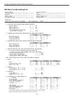
Wiring Schematic
SFS
LFS
ES
42
43
44
45
46
47
48
24VAC Com
DI12
DI11
DI10
DI9
DI8
DI7
49
50
51
52
53
54
55
56
DI 3/4/5/6/ Com
DI6
DI5
DI4
DI3
DI2
DI1
9VDC
J10
J9
2
3
1
PB2
Black (54)
Red (55)
Gray (56)
Pink (58)
Brown (57)
Gray (59)
Blue (45)
Blue (46)
Orange (47)
Gray (48)
Connect to R on TB
White (67)
White (66)
Blue (76A)
Blue (76B)
NOTE 1
NOTE 2
NOTE 4
NOTE 5
NOTE 8
Содержание RW Series
Страница 39: ...THIS PAGE INTENTIONALLY LEFT BLANK ...