


VFD68 Variable Frequency Drives
44
P. 34
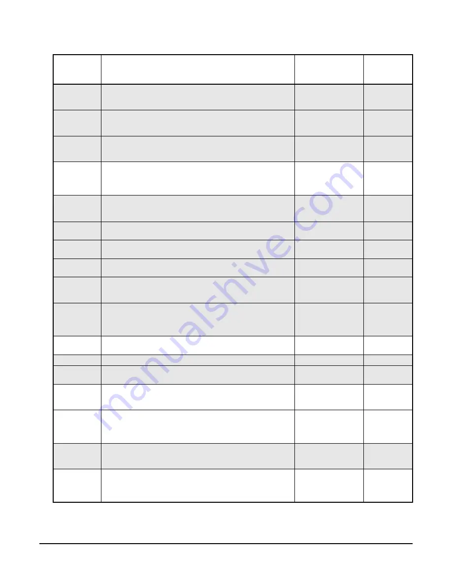
Frequency Jump 2B:
To avoid resonance noise caused by
natural frequency of mechanical system, enter frequency just
above
noisy frequency 2.
0 to 400 Hz, 9999
9999
P. 35
Frequency Jump 3A:
To avoid resonance noise caused by
natural frequency of mechanical system, enter frequency just
below
noisy frequency 3.
0 to 400 Hz, 9999
9999
P. 36
Frequency Jump 3B:
To avoid resonance noise caused by
natural frequency of mechanical system, enter frequency just
above
noisy frequency 3.
0 to 400 Hz, 9999
9999
P. 37
Speed Display:
Set the drive to display motor in RPMs
(instead of Hz) by entering the maximum rated motor speed
from the motor nameplate. When set to 0, the drive displays
speed in Hz.
0, 0.01–9998
0
P. 40
Run Key Rotation Direction:
Determines motor rotation
direction when you press the RUN key.
0 = forward rotation; 1 = reverse rotation
0,1
0
P. 57
Restart Coasting Time:
Determines the waiting time for a
restart after a power failure.
0.1–5
5 seconds
P. 58
Restart Cushion Time:
Determines the duration of linear
voltage ramp-up during a restart after a power failure.
0–40
25 seconds
P. 60
Energy Saving Control Selection:
Select 9 for energy-saving
operation that is optimized for fan and pump applications.
9
9
P. 65
Retry Selection:
Select 4 to allow the VFD to restart after most
conditions causing a trip (but not after thermal overload) while
the VFD operates/runs
4
4
P. 67
Number of Retries at Fault Occurrence
: The number of
consecutive retries that will occur after a fault occurs. If this
number is exceeded and the drive fails to start, then a Fault
Signal (ALM) will occur.
0–10
3
P. 68
Retry Wait Time:
Defines the time delay (in seconds), after a
fault shutdown, before the drive attempts to restart the motor.
0.1–600 seconds
10 seconds
P. 71
Applied Motor:
0: Standard motor; 13: Constant torque motor
0, 13
0
P. 72
PWM Frequency Selection:
Allows you to reduce audible
noise by changing the PWM frequency (Hz).
0 to 15
1
1
P. 73
Analog Input 1 Type:
Defines the input signal voltage range
and motor rotation direction. (0: 0–10 VDC,
1: 0–5 VDC, 10: 0–10 VDC, and 11: 0–5 VDC).
0, 1, 10, 11
1
P. 77
Parameter Write Select:
Enables or disables writing
(changing) certain parameters and defines when parameters
may be written (0: write when VFD stopped,
1: write disabled, 2: write enabled anytime).
0, 1, 2
2
P. 78
Reverse Rotation Prevention Select:
0= Both forward [STF]
and reverse [STR] allowed; 1=Reverse rotation [STR] disabled;
2=Forward rotation [STF] disabled
0, 1, 2
1
P.160
Extended Function Display Selection:
Defines whether to
display only simple parameters or all parameters (9999:
display only simple parameters;
0: display all parameters).
9999, 0
9999
Table 34: Basic and Advanced Parameter Descriptions for VFD68Bxx and VFD68Cxx Drives
(Part 2 of 4)
Parameter
Indication
on Monitor
Description
Range
VFD68xxx-
2 Defaults


