W A T E R - S O U R C E H E A T P U M P S
JRE-Series
R e v. : A u g u s t 1 9 , 2 0 2 0
I n s t a l l a t i o n , O p e r a t i o n , M a i n t e n a n c e
26
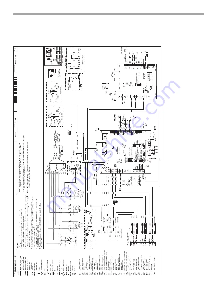
Typical Wiring Diagram – Typical Two Compressor Unit/DXM2
Страница 1: ...Water Source Heat Pumps Installation Operation Maintenance Supersedes Form 14808 NOM1 0820 97B0081N06 Issue Date August 19 2020 JRE Series Water Source Heat Pump MODELS JRE 3 20 Tons...
Страница 2: ...orized Water Valve 18 Electrical Data 20 Electrical Data Reheat or Internal Secondary Pump 21 TWD Units with MPC DDC Auxiliary Diagram 22 TWD Units with LON DDC Auxiliary Diagram 23 TWD Units with Eco...
Страница 3: ...EXTENDED RANGE STANDARD RANGE YES NO NO NO YES NO NO NO YES YES NO NO NO YES NO NO NO YES F MODULATING ENTHALPY ECONOMIZER F HOT GAS BYPASS REHEAT COIL 3 WAY MOTORIZED VALVE PROPORTIONAL CONTROL CIRCU...
Страница 4: ...uipment from pallets until equipment is required for installation Unit Protection Cover rooftop units on the job site Cap the open ends of pipes In areas where painting plastering roofing or the spray...
Страница 5: ...JRE036 072 Dimensional Data Optional Rain Hood Optional Rain Hood Pipe Chase Top View of Base S e r v i c e A c c e s s 3 5 1 1 m e t e r s Service Access 3 5 1 1 m eters Size Outdoor Air Opening Wate...
Страница 6: ...96 144 Dimensional Data Top View of Base Optional Rain Hood Optional Rain Hood S e r v i c e A c c e s s 3 5 1 1 m e t e r s Service Access 3 5 1 1 m eters Size Outdoor Air Opening Water In Out IPT JR...
Страница 7: ...tion Maintenance 7 JRE168 240 Dimensional Data Pipe Chase Optional Rain Hood Optional Rain Hood S e r v i c e A c c e s s 3 5 1 1 m e t e r s S e r v i c e A c c e s s 3 5 1 1 m e t e r s Top View of...
Страница 8: ...0 Installation Operation Maintenance 8 Standard Roof Curb Model A B C D E F JRE036 48 60 72 72 25 18 35 25 72 25 35 25 14 or 24 JRE096 120 144 82 25 21 41 25 82 25 41 25 14 or 24 JRE168 240 82 25 21 7...
Страница 9: ...ntenance 9 Standard Curb with Vibration Isolation Model A B C D E F JRE036 48 60 72 72 25 18 35 25 72 25 35 25 14 or 24 JRE096 120 144 82 25 21 41 25 82 25 41 25 14 or 24 JRE168 240 82 25 21 78 88 82...
Страница 10: ...T PUMPS JRE Series Rev Au gu st 19 2020 Installation Operation Maintenance 10 Side Discharge Supply Return Roof Curb Model A B C JRE036 48 60 72 72 25 18 35 25 JRE096 120 144 82 25 21 41 25 JRE168 240...
Страница 11: ...RGY EFFI C I E NC Y Installation Operation Maintenance 11 Side Discharge Supply Roof Isolation Curb Model A B C JRE036 48 60 72 72 25 18 35 25 JRE096 120 144 82 25 21 41 25 JRE168 240 82 25 21 78 88 N...
Страница 12: ...ss to the unit side panels and all electrical connections Follow these guidelines when installing the curb 1 Set unit on curb 2 Align unit so that return air and supply air in the unit match return an...
Страница 13: ...osed geothermal loop GLHP GWHP Pipe joint compound is not necessary when Teflon threaded tape is pre applied to hose assemblies or when flared end connections are used If pipe joint compound is prefer...
Страница 14: ...de Levels 10 C 24 C 38 C Copper Cupronickel 20ppm NR NR 150 ppm NR NR 304 SS 400 ppm 250 ppm 150 ppm 316 SS 1000 ppm 550 ppm 375 ppm Titanium 1000 ppm 550 ppm 375 ppm Erosion and Clogging Particulate...
Страница 15: ...accept other types of conductors Figure 2 illustrates a typical trap used with JRE Heat Pumps Multiple units within the same zone should be operated from a common temperature control Thermostat Wirin...
Страница 16: ...eratures below 60 F 15 6 C must include the optional water refrigerant circuit insulation package to prevent internal condensation Figure 3 LT1 Limit Setting Alarm Relay Comp Relay O Y2 W G C R AL1 24...
Страница 17: ...ing OFF OFF ON Humidifier ON ON OFF Outside air damper All other DIP combinations are invalid A slow closing valve may be required to help reduce water hammer Figure 4 shows typical wiring for a 24VAC...
Страница 18: ...5 Valve Wiring Figure 6 Typical Valve Wiring From Water Source IN OUT NOTE Shut off valves strainers and other required components not shown Solenoid Valve Flow Regulator To Discharge Stage 1 Stage 2...
Страница 19: ...Thermostat wire must be 18 AWG wire Representative thermostat wiring is shown in Figure 8 however actual wiring connections should be determined from the thermostat IOM and or unit wiring diagram Pra...
Страница 20: ...D E 2 13 7 83 1 1 9 2 3 0 36 6 N A N A 40 0 50 F 460 3 60 414 506 A B C 2 6 2 41 0 1 3 1 2 0 15 5 N A N A 17 0 20 F 460 3 60 414 506 D E 2 6 2 41 0 1 4 3 3 0 16 7 N A N A 18 3 20 N 575 3 60 518 633 A...
Страница 21: ...N 575 3 60 518 633 A B C 2 4 8 33 0 1 2 3 2 0 1 0 44 12 3 N A N A 13 5 15 N 575 3 60 518 633 D E 2 4 8 33 0 1 3 4 3 0 1 0 44 13 4 N A N A 14 6 15 JRE120 H 208 3 60 197 254 A B C 2 15 6 110 0 1 9 2 3...
Страница 22: ...WATER SOURCE HEAT PUMPS JRE Series Rev Au gu st 19 2020 Installation Operation Maintenance 22 Typical Wiring Diagram Units with MPC DDC Option Auxillary Diagram...
Страница 23: ...JRE Series Rev Au g u st 19 2020 THE SMART SOLUTION FOR ENERGY EFFI C I E NC Y Installation Operation Maintenance 23 Typical Wiring Diagram Units with LON DDC Option Auxillary Diagram...
Страница 24: ...WATER SOURCE HEAT PUMPS JRE Series Rev Au gu st 19 2020 Installation Operation Maintenance 24 Typical Wiring Diagram Units with Economizer Auxillary Diagram...
Страница 25: ...OLUTION FOR ENERGY EFFI C I E NC Y Installation Operation Maintenance 25 Typical Wiring Diagram Single Compressor DXM2 PMP3 460 volt units with Internal Secondary or Circulating Pump for Condenser Hot...
Страница 26: ...WATER SOURCE HEAT PUMPS JRE Series Rev Au gu st 19 2020 Installation Operation Maintenance 26 Typical Wiring Diagram Typical Two Compressor Unit DXM2...
Страница 27: ...ion modes Minimum entering air temperature while operating in the heating mode not continuous fan is the minimum entering air temperature for the standard model without the reheat option in the heatin...
Страница 28: ...t does not impact room temperature Competitors without hydronic reheat typically use an on off non modulating refrigeration based reheat circuit typically referred to as Hot gas reheat HGR HGR needs h...
Страница 29: ...2 13 24 145 6 7 6 22 5 0 3 0 7 104 8 78 4 12 40 147 1 8 5 30 0 1 4 3 2 107 2 79 1 12 00 148 1 8 9 120 15 0 0 1 0 1 94 8 76 6 14 59 144 6 6 5 22 5 0 3 0 7 98 5 76 9 13 67 145 1 7 2 30 0 1 3 3 0 100 5 7...
Страница 30: ...ith the compressor contactor s and blower relay In the heating mode the reversing valve is de energized Almost any thermostat will activate the heat pump in heating or cooling modes The DXM2 microproc...
Страница 31: ...tional control to drive the motorized valve during the reheat mode of operation The Motorized Valve is a proportional actuator three way valve combination used to divert the condenser water from the c...
Страница 32: ...26 425 0 30 0 28 0 30 0 28 450 0 31 0 29 0 32 0 29 475 0 33 0 31 500 0 35 0 32 525 0 37 550 0 38 575 0 40 Example Reheat coil loss can be determined from the above table Coil velocity FPM Airflow CFM...
Страница 33: ...from the coil Note If the reheat sensor located in the supply air stream is above 70 F it must be disabled to allow the modulating valve to shift Disable this sensor by removing the white wire from th...
Страница 34: ...tering Fluid 120 F 48 9 C 90 F 32 2 C Operating Limits Environment Units are designed for roof mount or indoor installation Power Supply A voltage variation of 10 of nameplate utilization voltage is a...
Страница 35: ...l the system and bleed off all air 10 Add antifreeze to the system in climates where ambient temperature falls below freezing using the proportion of antifreeze shown in Table 5 The volume of antifree...
Страница 36: ...able sheave on fan motor and open sheave to desired position Retighten set screw and replace belt and set belt tension as below Belt Tensioning An overly loose belt will upon motor start produce a sli...
Страница 37: ...emove the tension checker and read the forct applied from the bottom of the small O ring on the deflection force scale 6 Compare the force you have applied with the values given in the table below The...
Страница 38: ...orrosion in the system piping Unit Filters To avoid system damage ensure that the unit filter is clean Unit Fans Manually rotate fans to assure free rotation Ensure that fans are properly secured to t...
Страница 39: ...ifreeze solution Table 6 Operating Temperatures and Pressures 3 Operate each heat pump in the heating cycle imme diately after checking cooling cycle operation A time delay will prevent the compressor...
Страница 40: ...y system failures complete the following checks and data entries before the system is put into full operation External Static Sheave Setting Turns Temperatures F or C Antifreeze Pressures PSIG or kPa...
Страница 41: ...ION To avoid fouled machinery and extensive unit cleanup do not operate units without filters in place Do not use equipment as a temporary heat source during construction WARNING WARNING When replacin...
Страница 42: ...WATER SOURCE HEAT PUMPS JRE Series Rev Au gu st 19 2020 Installation Operation Maintenance 42 Notes...
Страница 43: ...JRE Series Rev Au g u st 19 2020 THE SMART SOLUTION FOR ENERGY EFFI C I E NC Y Installation Operation Maintenance 43 Notes...
Страница 44: ...improve its products As a result the design and specifications of each product at the time for order may be changed without notice and may not be as described herein Please contact Johnson Controls C...