background image

FRICK

®

 QUANTUM

™ 

HD VILTER

®

 RETROFIT

INSTALLATION INSTRUCTIONS

090.040-I02 (AUG 2014)

page 7

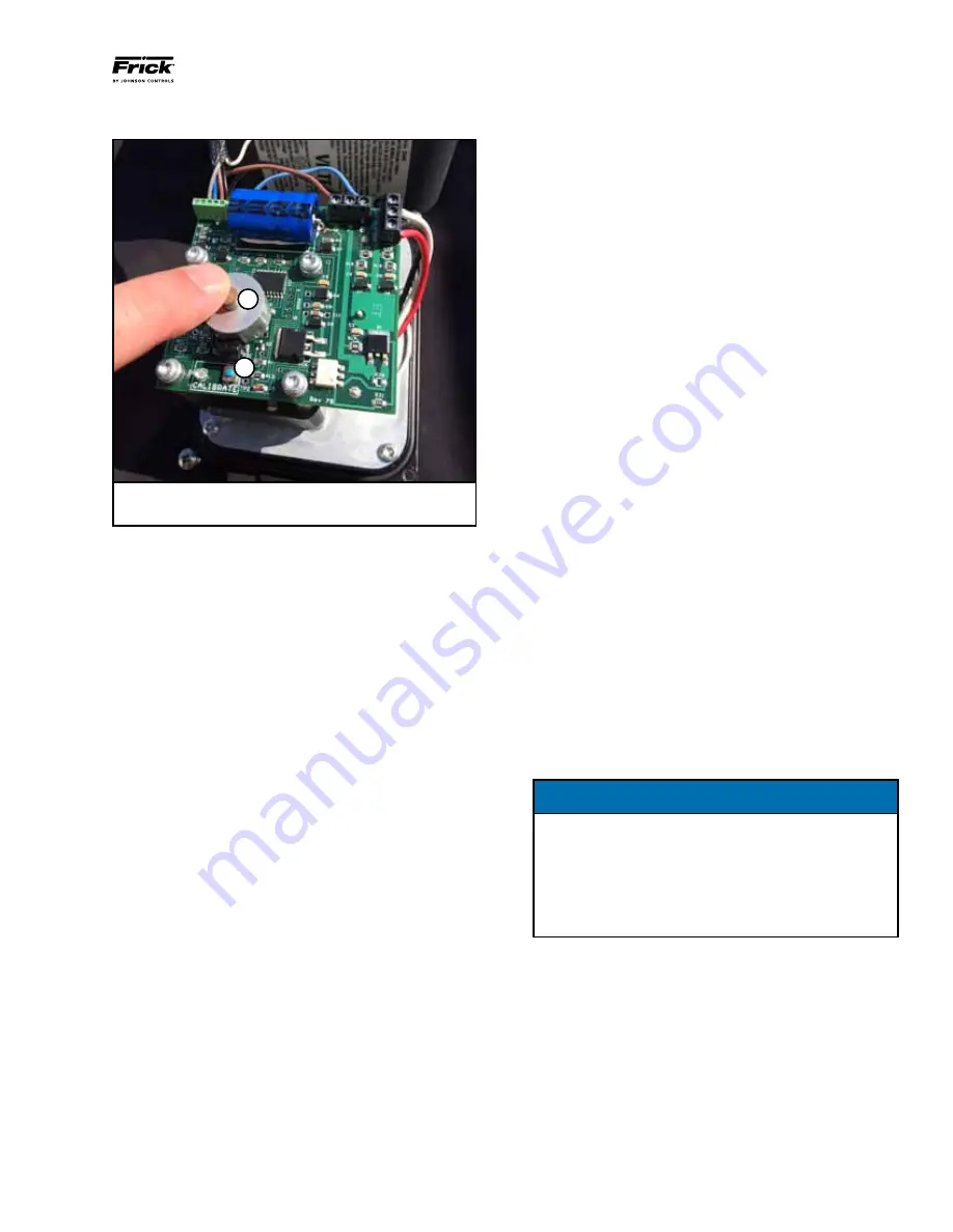
A

B

A. Photo Chopper

B. Calibration Button & LED

Figure 4. Actuator Control Board
Start with the Capacity Slide actuator

1.  Press the blue calibration button on the actuator control 

board. The red LED will begin flashing at a fast rate. 

2.  Touch the Unload Capacity button on the 

QUANTUM

HD


calibration page to drive the capacity slide to its minimum 
physical  position.  Watching  the  photo-chopper  on  the 
actuator control board it will be evident when the capac-
ity slide is at the physical stop as the photo chopper will 
suddenly slow and stop. 

3.  Quickly touch the Unload Capacity button to stop sending 

the unload signal to the actuator. 

4.  Press down on the photo-chopper to relieve the tension
5.  Touch the Load Capacity button and then again with a 1 

second differential to move the capacity slide just off it's 
minimum position and relief any stress on the command 
shaft. 

6.  Touch the blue calibration button on the actuator. Once 

the red LED starts flashing at a slower rate touch the Set 
Low Capacity button on the Quantum HD calibration page.

7.  Touch the Load Capacity button to drive the capacity slide 

to it's physical maximum position. This will be complete 
when  the  photo-chopper  suddenly  slows  and  stops. 
Quickly touch the Load Capacity button to stop sending 
the load signal to the actuator. Press down on the photo-
chopper to relief the tension. 

8.  Touch the Unload Capacity button and then again with a 1 

second differential to move the capacity slide just off it's 
maximum position and relief any stress on the command 
shaft. 

9.  Press the blue calibration once more. The red LED should 

stop flashing indicating that calibration of the actuator 
is complete. Touch the Set High Capacity button on the 

QUANTUM

HD 

calibration screen to complete the calibra-

tion of the capacity slide.

Calibrate the Volume Slide actuator

1.  Press the blue calibration button on the actuator control 

board. The red LED will begin flashing at a fast rate. 

2.  Touch the Decrease Volume button on the 

QUANTUM

HD


calibration page to drive the volume slide to it's minimum 
physical  position.  Watching  the  photo-chopper  on  the 
actuator control board it will be evident when the volume 
slide  is  at  the  physical  stop  as  the  photo  chopper  will 
suddenly slow and stop. 

3.  Quickly touch the Decrease Volume button to stop sending 

the decrease signal to the actuator. 

4.  Press down on the photo-chopper to relieve the tension.
5.  Touch the Increase Volume button and then again with a 

1 second differential to move the volume slide just off it's 
minimum position and relief any stress on the command 
shaft. 

6.  Touch the blue calibration button on the actuator. Once 

the red LED starts flashing at a slower rate touch the Set 
Low  Volume  button  on  the 

QUANTUM

HD

  calibration 

page.

7.  Touch the Increase Volume button to drive the volume 

slide  to  it's  physical  maximum  position.  This  will  be 
complete when the photo-chopper suddenly slows and 
stops. Quickly touch the Increase Volume button to stop 
sending the increase signal to the actuator. Press down 
on the photo-chopper to relief the tension. 

8.  Touch the Decrease Volume button and then again with a 

1 second differential to move the volume slide just off it's 
maximum position and relief any stress on the command 
shaft. 

9.  Press the Blue calibration once more. The red LED should 

stop flashing indicating that calibration of the actuator 
is complete. Touch the Set High Volume button on the 

QUANTUM

HD 

calibration screen to complete the calibra-

tion of the Volume slide.

NOTICE

The  capacity  and  volume  slides  are  prevented  from 
physically hitting their mechanical/physical stops after 
calibration is complete.
To  do  this,  the  software  clips  the  range  of  these 
devices at each end by 2% of the bit count when the 
calibrate  high  and  calibrate  low  end  buttons  are 
pushed on the capacity/volume calibration page.

For additional sensors not provided with the retrofit kit, refer 
to the OEM instructions regarding the sensor power require-
ment, signal type, signal range, and calibration process.
This completes the 

QUANTUM

HD

 retrofit instructions.

Содержание Frick QUANTUM HD VILTER

Страница 1: ...ck for the latest version of this publication Contents Vilter Retrofit Installation Instructions Frick Quantum HD Retrofit Panels 2 Introduction 2 Instructions 3 Calibration of Temperature Pressure Sensors 6 Calibration of Capacity Volume Slides 6 Installation Of Electronic Equipment Wire Sizing 8 Voltage Source 8 Grounding 9 VFD Applications 9 Conduit 10 Wiring Practices 10 Communications 12 UPS ...

Страница 2: ...ONTROL PANEL These instructions are based on the installer having a fun damental knowledge of refrigeration design and installation Instructions are for conversion to the standard design unit Special package and or control modifications furnished on the existing unit will require deviation from these instructions Contact Frick if you have any questions concerns or prob lems Frick does not take res...

Страница 3: ...eat venting and recovery procedure if neces sary 4 If an oil separator temperature probe well is to be installed drain the oil from the oil separator 5 Take digital photographs of all internal connections of the existing controller to use as a reference when making the connections on the replacement controller Remove the existing panel from the compressor package DO NOT CUT WIRES OR TUBING LINES T...

Страница 4: ... to be replaced with the optical actuators before proceeding The position feedback cable from the capacity and volume slide actuators will be routed back to the QUANTUM HD and through 2 of the 4 holes in the 3 4 strain relief that is provided The capacity slide actuator is the one that is physically higher on the compressor To avoid any incidental damage disconnect the cables for control and signa...

Страница 5: ...12 24 vdc is labeled with the part number and acceptable voltage output range The voltages for the 5 12 24 vdc supplies are as follows 5 vdc range 5 10 5 20 vdc 12 vdc range 12 10 12 20 vdc 24 vdc range 24 2 24 5 vdc The power supplies accept both 120 or 220 VAC input range 100 240 VAC 24 At this point the operating display on the controller should be seen Log in to the controller using a default ...

Страница 6: ...n procedure using the value from the gauge 13 Step to the pre oil filter pressure setting on the Pressure Calibration display Calibration of Capacity Volume Slides Go to Menu Calibration Capacity Volume Once on this screen you can attach the power and signal cables at the optical actuators for the capacity and volume slides The optical actuators used for capacity and volume slide positioning provi...

Страница 7: ... board The red LED will begin flashing at a fast rate 2 Touch the Decrease Volume button on the QUANTUM HD calibration page to drive the volume slide to it s minimum physical position Watching the photo chopper on the actuator control board it will be evident when the volume slide is at the physical stop as the photo chopper will suddenly slow and stop 3 Quickly touch the Decrease Volume button to...

Страница 8: ...pressor package or a Central Control System panel NOTICE It is very important to read the installation instructions thoroughly before beginning the project Make sure you have drawings and instructions with your equipment If not call the manufacturer and request the proper instructions and drawings Every manufacturer of elec tronic equipment should have a knowledgeable staff willing to answer your ...

Страница 9: ... must also be insulated to avoid inadvertent contact at multiple points to ground which could create Ground Loops In many installations that are having electronic control prob lems this essential wire is usually missing is not insulated or improperly sized NEC size ratings are for safety purposes and not necessarily for adequate relaying of noise EMI to earth ground to avoid possible interference ...

Страница 10: ...tage lines in PVC does not reduce these requirements on separation Only running in metal conduit can relieve these requirements Due to the level of EMI that can be induced onto lower voltage lines when running multiple feeders in a trench control power communications analog or signal wiring cannot be run in trenches that house multiple conduits electrical ducts carrying 3 phase power to starters v...

Страница 11: ...e conduit and the enclosure so that if water gets on top of the enclosure it cannot run in between the conduit and the enclosure This is extremely important in outdoor applications NOTICE It is simply NEVER a good practice to enter through the top of an electronic control panel or starter panel that does not already have knockouts provided If knockouts are not provided for this purpose it is obvio...

Страница 12: ...c does not advise nor support the use of uninterrupted power supply systems for use with the Quantum HD panel With a UPS system providing shutdown protection for a Frick Quantum panel the panel may not see the loss of the 3 phase voltage on the motor because the UPS may prevent the motor starter contactor from dropping out With the starter contactor still energized the compressor auxiliary will co...

Отзывы: