


IDC INDUCED DRAFT EVAPORATIVE CONDENSERS
INSTALLATION - OPERATION - MAINTENANCE
S140-500 IOM (FEB 08)
Page 4
1.5 Safety
Requirements
IDC unit installation, operation, and maintenance – involves
heavy rotating machinery operating at high speed and high
voltage. Normal operations and maintenance procedures
may require working at elevations, enclosed space entry,
or use of hand and power tools. With these considerations,
safety must be the top priority in all activities with this evapo-
rative cooling product.
Imeco recommends that every client analyze and develop
an installation-specifi c safety regime that takes into account
such variables as specifi c site/system features, personnel
qualifi cations, hazard identifi cation, etc. The following ele-
ments of operational safety are recommended for inclusion
in every client’s IDC condenser safety plan/requirements:
Electric:
Confi gure all power switches and controls to pro-
vide an open, safe circuit before and during maintenance
procedures, until the unit is cleared by management for
normal on-line operations. For extended shutdowns it is
recommended that a qualifi ed technician remove fuses from
“fused-disconnect panels” or otherwise open the circuit in an
accepted, secure manner.
Fans
- All fan covers, guards, and shaft retainers (if any)
must be in place before applying power to an IDC condenser.
Always disengage and lock out power before allowing interior
inspections. To prevent foreign objects from being drawn
into rotating fan blades,
never
allow operation with hatch
off/open.
Enclosed space inspections
– Inspections of condenser
coil, drift eliminators, etc., requires machinery lockout and
the use of a “lookout buddy” at a minimum. Consult your
internal safety policy and OSHA requirements for additional
safety rules/procedures.
Vibration and noise
– Discontinue or stop machinery that
emits unusual vibration and noise. The source must be
investigated (and apparent discrepancies corrected) before
testing or placing the unit back in operation.
Wet Surface Precautions
– Poorly maintained/wetted
machinery requires care to avoid electrical shocks from in-
adequate/loose fi eld wiring/connections. All personnel must
lock out and tag machinery before working on the condenser.
Proper safety precautions such as the use of insulating
soles/gloves and a trained “lookout buddy” are indispensable.
Ice formation in cold weather can present fall/slip hazards.
Icing safety procedures should be mandatory when the daily
ambient temperature falls below 40°F (4.4°C).
Section 1.0 Pre-Installation
1.1 Preface
The evaporative-cooled, Induced Draft Condenser (IDC)
you have purchased utilizes the fi nest in engineered design,
materials, and corrosion protection to provide a rugged, long-
lasting unit. This manual provides the information needed for
safe installation, operation, and maintenance. Close attention
to the instructions and guidelines provided in this manual will
ensure a long satisfactory unit life and dependable operation
and performance.
Before rigging or beginning work on the unit, Imeco recom-
mends that experienced Refrigeration contractors, opera-
tors, and maintenance technicians be formally trained on
the IDC design and features - with this manual’s reading
as a
minimum
requirement. After installation, the unit (as
selected) must also be properly connected to appropriately
designed and installed refrigeration and water treatment
systems. The engineering plans, piping layouts, etc. for the
IDC and associated system components must be detailed in
accordance with local/governing codes and the best industry
standards and practices such as those outlined in up-to-date
industry literature.
Should you have any comments or questions regarding this
manual or the IDC unit, you are urged to call your local sales
representative.
1.2 Shipment
Inspection
Upon arrival of the IDC condenser at the job site, the unit
should not be signed for until it is inspected to ensure that all
required parts have been received and are free of shipping
damage. Unpack all items and check against shipping lists
- any items that appears to be missing should be noted on
the shipping papers and reported to an Imeco representative.
The following parts should be inspected:
•
Sheaves, belts, bearings/supports
•
Fan blades, shaft, and motor/hood
•
Coil/s and water distribution spray header, pump,
strainers, and fl oat assembly
•
Drift eliminators and inlet louvers
•
Parts shipped loose in pan section
Parts shipped loose include fan guard, inlet louvers, assorted
nuts, bolts, washers, and mastic strip (a fl exible joint seal
stored on a continuous paper-backed roll). Accessory items
will likely be shipped “loose” in a sealed box that is secured
in the pan section.
1.3 Transit Damage Claims
The IDC unit owner’s authorized agent who signs for the
shipment is responsible for making damage claims (per
ICC requirement). Request immediate inspection and form
execution by the agent of the carrier. Contact YORK Re-
frigeration Systems (815-288-3859) to report damage or
shortage claims.
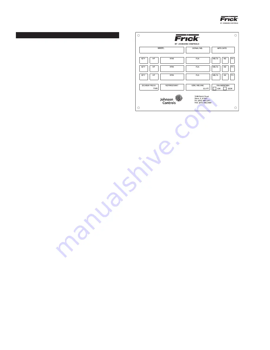
1.4 Unit
Identifi cation
All IDC units are identifi ed by a nameplate permanently at-
tached to the pan section.
Figure 1-1. ID Plate Information
shows the information provided. Imeco recommends that
the name plate data be copied onto the graphic for ease of
reference ordering parts.
NOTE: When inquiring about the unit or ordering repair
parts, provide the MODEL and SERIAL NUMBERS from
the data plates.
Figure 1-1. ID Plate Information