FILTER PARAMETERS (MAIN MODE) | 29
FILTERS 1-4
Filters
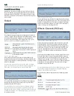
Figure 40. Filter Panel
Filters 1-4
Solaris has four filters that can be routed in parallel or
series. Any signal can be passed to a filter, though a typical
configuration might have a mixer output routed to a filter
input.
To route 2 or more filters in series, simply select
the first filter in the series as the input to the next
filter, and so on.
The signal for each filter is sent to its own dedicated VCA,
where its pan position and level can be set. Each VCA can
be controlled by a different envelope, but the EG6 (VCA)
has the final “say” for the overall output. Using separate
envelopes, you can create articulated shapes for each fil
-
ter’s output; almost a “multi-timbre” approach to the sound,
enhanced by the fact that each can also have its own enve-
lope and pan position.
With the filter outputs as possible signal inputs to other
filters, you can create feedback loops within each filter
section, or place multiple filters in series. You also can get
some useful and strange distortion of the filters if desired,
among many, many other things!
Filter Parameters (Main Mode)
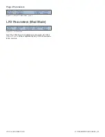
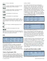
Page 1 Parameters
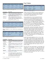
Figure 41. Filter Main Mode, page 1
Type
Type of filter. Refer to “Appendix 3- Filter Types” on page
56 for a comprehensive list of the filter types available in
Solaris.
Mode
Several of Solaris’s filter types support multiple modes of
operation, such as lowpass, highpass, bandpass, band
reject (notch), or combinations of those in series. Some
filter types also support different pole configurations. Refer
to “Filter Types” on page 56 for details.
Cutoff
The filter’s cutoff frequency, in semitones from 0.0 to 126.0.
Recall from “Knob Acceleration and the Shift Button” on
page 16, that the
Cutoff
knob is designed to sweep
quickly through its values. For fine control over cutoff
frequency, use the
Data Wheel
(or press and hold the Shift
button while turning the
Cutoff
knob) to make adjustments
in 1/10 semitone increments.
Resonance
Resonance control. Each filter type will have a different
resonance characteristic, so you will need to adjust this as
you change the filter type.
Damp
If you are working with a Comb Filter, this parameter ad-
justs a 6 dB LP filter in the feedback circuit.
X-Fade
If Vocal filter type is selected, this parameter adjusts the po
-
sition of the signal in the five vowel field.
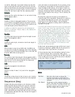
Page 2 Parameters
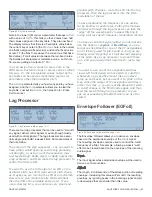
Figure 42. Filter Main Mode, page 2
Typically, the input to a filter will be a sound source such
as a mixer output or the output directly out of an oscillator
or Insert FX. Because Solaris’s filter can take almost any
signal as an input, very interesting effects can be created
by routing control signals through the filters as well.
KeyTrk
Keyboard tracking causes the filter to “open” in relation to
the note number played. With large positive values, notes
played higher on the keyboard will sound brighter because
the filter’s cutoff frequency has been increased relative to
the
KeyTrk
parameter’s value and the
KeyCntr
.
KeyCntr
The key center parameter determines which MIDI note
number is considered the center of the keyboard, which af-
fects how keytracking is applied.
Содержание Solaris
Страница 1: ...User Guide Version 1 ...


