


7
Important Information
2.2 Gas connection and selection
Gas hoses, regulator and gas cylinder connections
•
Connect one end of the gas hose (1) to the gas solenoid
valve on the back panel of the welder (2).
•
Connect the other end of the gas hose to the regulator (3)
connected to the shielding gas cylinder (4).
JM-1998594-02
4
5
6 8
3
7
2
1
•
Slowly open the cylinder valve (5) by turning it counter-
clockwise until the cylinder pressure gauge (6) displays a
fixed cylinder pressure.
•
Slowly turn the flow adjustment knob (7) of the gas flow
gauge (8) clockwise to increase gas flow to 20 cfm. Turn it
counter-clockwise to reduce the gas flow.
•
Gas flow can be heard at the end of the gun when the
trigger is activated.
Note:
If there is no gas flow, a harsh arc with excessive
spatter will result and a smooth weld bead will not be
obtained.
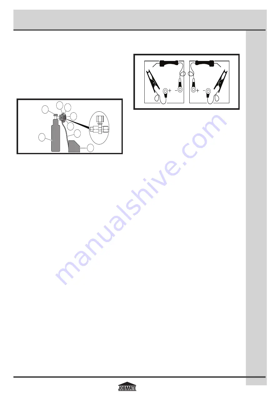
Polarity changing
Factory polarity setting (electrode negative) is for flux-core
welding (no shielding gas is required). In this process the RED
gun lead is connected to the negative ("-") polarity terminal
and the ground cable is connected to the positive ("+")
terminal.
For MIG welding (solid wire) using shielding gas, the RED gun
lead is connected to the positive ("+") and the ground cable is
connected to the negative ("-") terminal.
JM-1998594-03
NO
GAS
GAS
Gas selection
Different materials require different shielding gas when
MIG welding. Refer to the set up chart inside the wire drive
compartment.
Mild steel:
Use 75% argon and 25% CO
2
for reduced spatter
and reduced penetration for thinner materials. Use a higher
percentage of CO
2
for deeper penetration and increased spatter.
Note:
Do not use argon gas concentrations higher than
75% on steel. The result will be extremely poor penetration,
porosity, and brittleness of a weld.
Stainless steel:
Use a mixed gas consisting of helium, argon,
and CO
2
.
Aluminium or bronze:
Use 100% argon.