


18
Operating Instructions
•
Fillet weld joint:
Most fillet weld joints on metals of
moderate to heavy thickness will require multiple pass welds
to produce a strong joint. The sequence of lying multiple pass
beads into a T fillet joint and a lap fillet joint is shown below
(fig Z).
fig Z
1
1 2
3
2
3
Lap Joint Welded
In Three Passes
T Join in
Three Passes
JM-1998594-30
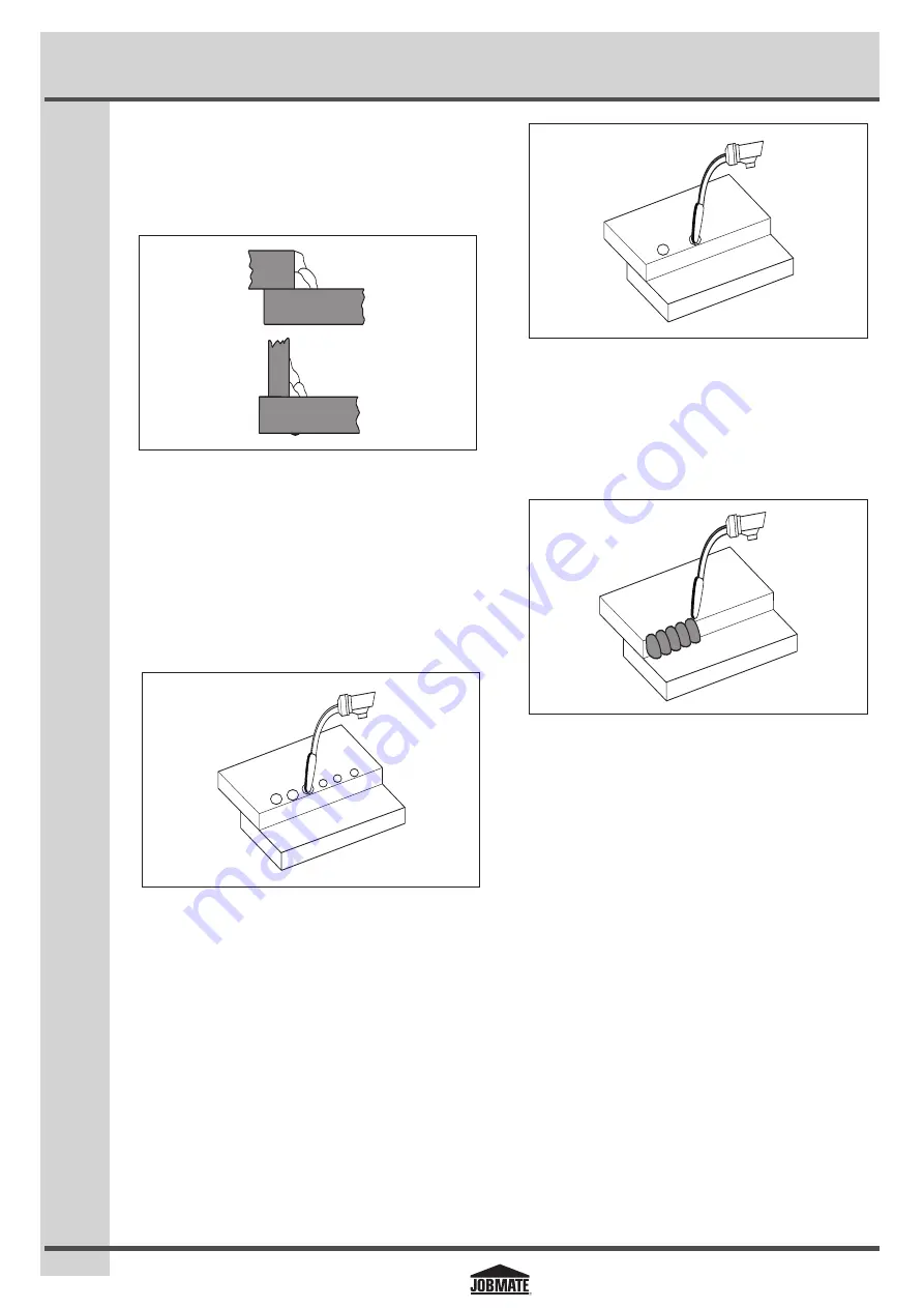
6.8 Spot welding
There are three methods of spot welding:
1.
Burn-through method:
In this method, two overlapped
metal pieces are welded together by burning through the
top piece and into the bottom piece. The wire suitable for
this method is a 0.035 inch self-shielding, flux-core wire.
Always select the high heat setting for this method and tune
in the wire speed prior to making a spot weld (fig a).
fig a
JM-1998594-31
Note:
Do not use a 0.030 inch self-shielding flux-core
wire when using this method unless the metal is very
thin, or excessive filler metal and minimal penetration are
acceptable.
2.
Punch and fill method:
This method produces a weld
with the most finished appearance. In this method, a hole
is punched or drilled into the top piece of metal and the arc
is directed through the hole to penetrate into the bottom
piece. The puddle is allowed to fill up the hole leaving a spot
weld that is smooth and flush with the surface of the top
piece (fig b).
fig b
JM-1998594-32
3.
Lap spot method:
The welding arc is directed to penetrate
the bottom and top pieces at the same time, and along each
side of the lap joint seam. Select the wire diameter, heat
setting, and tune in the wire speed so they are suitable for
welding the material with a continuous bead (fig c).
fig c
JM-1998594-33
Spot welding procedure
1. Select the wire diameter and heat setting recommended
above for the intended method of spot welding.
2. Tune in the wire speed as if a continuous weld is to be
performed.
3. Hold the nozzle piece completely perpendicular to and about
¼ inch off the workpiece.
4. Pull the trigger on the torch and release it when the desired
penetration is achieved.
5. Make practice spot welds on scrap metal and vary how long
the trigger is held until a desired spot weld is made.
6. Make spot welds on the actual workpiece at desired locations.