


13
Assembly Instructions
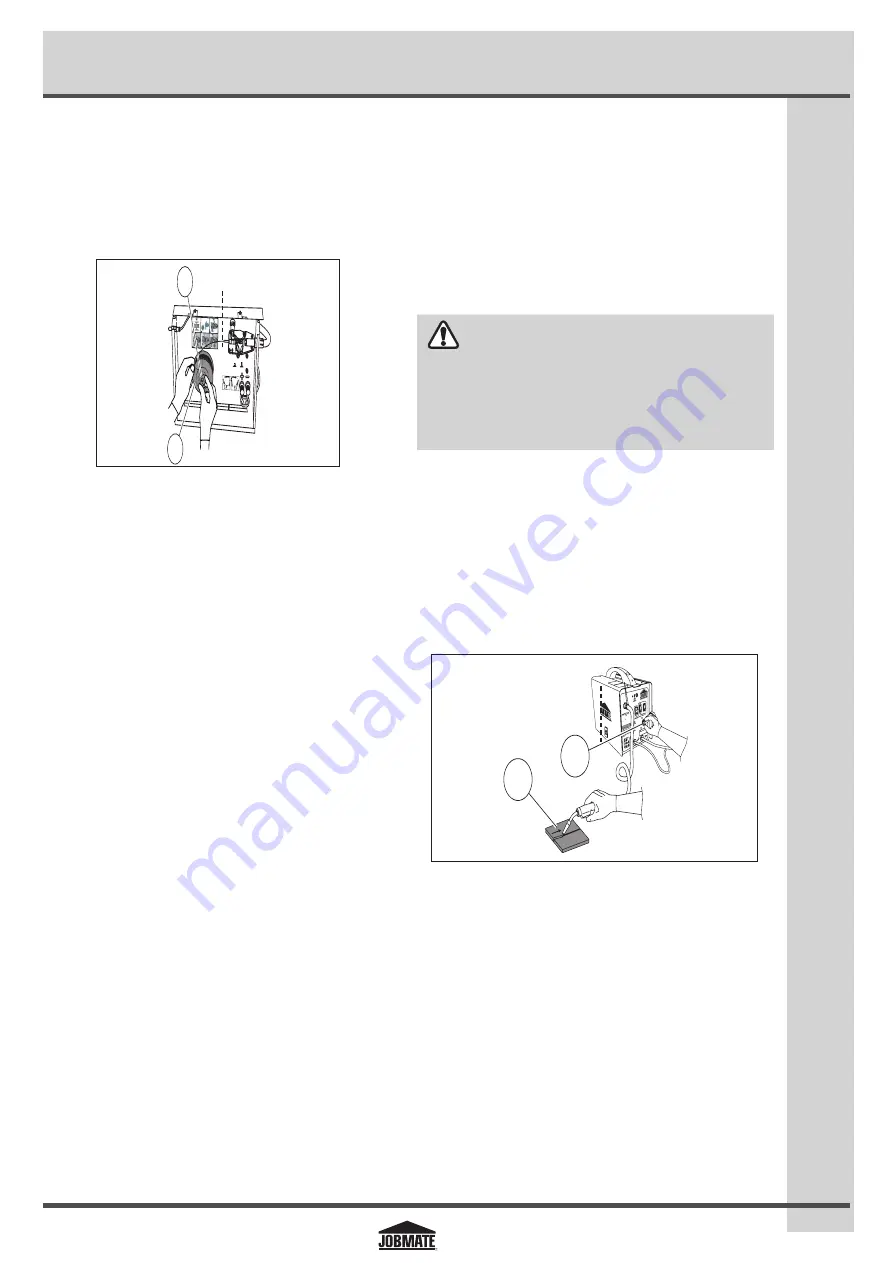
5. Setting the wire spool tension:
a. Turn the wire spool (1) with one hand (fig I).
b. Increase the spool tension by tightening the wing nut (2)
while turning the spool. Turn the spool until it slows down
(fig I).
JM-1998594-13
fig I
NORMAL
NORMAL OVER CURRENT
SURINTENSITEE
ATTENTION: LE
CA
DE SOUDAGE
NO
GAS
GAS
1
2
3
4
6
5
1
2
c. Stop tightening the wing nut.
d. Repeat the above steps until proper spool tension is
achieved.
Note:
If high tension is applied to the wire spool, the wire slips
away from the drive roller groove. If less tension is applied, the
wire spool unspools itself when the trigger is released. Use the
wing nut to adjust the spool tension high or low.
6. Disconnect the welder from the power source, and remove
the leading end of the wire from the spool.
7. Cut off any bent portion of the wire using a wire cutter.
8. Loosen the tension adjusting knob holding the drive
tension arm in place and lift the tension arm up off the
drive roller.
9. Insert the wire into the inlet guide tube, and feed about
six inches of it across the drive roller and into the torch
assembly.
10. Line up the wire with the correct groove in the drive roller.
11. Place the drive tension arm above the drive roller.
12. Tighten the drive tension adjusting knob until the tension
roller is applying enough force on the wire to prevent it
from slipping in the drive roller.
13. Plug in and turn the welder ON. Set the voltage switch to
the voltage setting recommended for the gauge of metal
that is to be welded. Refer to page 11 for set up chart on
the back side of the wire drive compartment.
14. Set the wire speed control. Straighten the MIG gun cable
and pull the trigger in the gun handle to feed the wire
through the torch assembly.
15. Turn the power switch to the OFF position. Select a contact
tip that has the same diameter as the wire being used.
Note:
Due to inherent variances in flux-core welding wire, it is
necessary to use a larger-sized contact tip than the wire.
16. Slide the contact tip over the wire, thread the contact tip
into the end of the gun and tighten securely.
17. Install the nozzle onto the gun assembly, and cut off excess
wire that extends past the end of the nozzle.
WARNING
ENSURE THAT WIRE PASSING OUT OF THE END OF THE TORCH
DOES NOT CONTACT THE WORKPIECE, GROUND CLAMP OR ANY
GROUNDED MATERIAL DURING THE DRIVE TENSION SETTING
PROCESS, AS DOING SO MAY REDUCE THE RISK OF ARC FLASH.
5.4 Setting the wire feed speed
1. To set the wire feed speed, initiate the welding operation
using the scrap workpiece (1).
2. While welding the scrap workpiece, turn the wire speed
adjustment knob (2) clockwise, and increase the wire
speed until the wire seems to feed smoothly without
slipping (fig J).
JM-1998594-14
1
2
WIRE FEE
D
ENTRAI
NEMEN
T
199-859 6
SOUDEUSE A D V
IDAGE
DE FIL- LECTRO
DE SOUS
GAZ
MIG/FLUX
-CORE WI
RE FEED WELDER
INERTE OU A AM
E EN FLU
X
1
2
3
4
5
6 7
8
WARN
ING/A
VERT
ISSE
MEN
T
. This
weld
er is
for u
se on
a 20
A br
anch
circu
it.
DO N
OT REM
OVE
THIS
LAB
EL /
N’EN
LEVE
Z PAS
CET
TE ÉT
IQUE
TTE.
. If co
nnec
ted t
o a c
ircuit
prot
ected
by fu
ses,
use a
time
-dela
yed f
use m
arked
“D”.
. Cet
te so
udeu
se re
quier
t un c
ircuit
de 2
0 A.
. Se l
a sou
deus
e est
bran
chée
á un
circu
it pro
tégé
par f
usibl
es, u
tilise
z un
fusib
le
tem
poris
é ma
rqué
<< D
>>.
1
fig J
2