


SECTION 6 - JLG CONTROL SYSTEM
3121290
– JLG Lift –
6-55
8/4
(Continued)
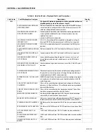
TWR LENGTH SENSOR TWO VALUE
OUT OF RANGE HIGH
This fault is reported by the Ground module when the length sensor
value is outside the constant data limit
TWR LENGTH SENSOR TWO VALUE
OUT OF RANGE LOW
This fault is reported by the Ground module when the length sensor
value is outside the constant data limit
TWR ANGL1 INVALID ANGLE
Tower boom angle sensor #1 out of range
TWR ANGL2 INVALID ANGLE
Tower boom angle sensor #2 out of range
INVALID ANGLE SENSOR #1 MODEL Wrong tower angle sensor Mfgr. Installed on a 1250AJP (Must be a
Rieker, not Spectron)
INVALID ANGLE SENSOR #2 MODEL Wrong tower angle sensor Mfgr. Installed on a 1250AJP (Must be a
Rieker, not Spectron)
MAIN ANGL1 INVALID ANGLE
Main boom angle sensor #1 out of range
MAIN ANGL2 INVALID ANGLE
Main boom angle sensor #2 out of range
MAIN ANGLE SENSOR NOT
DETECTING ANGLE CHANGE
The main boom is being commanded to move and the main angle
sensors are not detecting any movement
MAIN ANGLE MOVEMENT WITH-
OUT CMD
The main boom angle is changing without a main lift command
WRONG TWR TELE RESPONSE
The tower telescope is moving in the opposite direction the user is
commanding.
WRONG TWR LIFT RESPONSE
The tower lift is moving in the opposite direction the user is com-
manding
TWR CYL ANGLE SENSOR OUT OF
RANGE LOW
The tower cylinder angle sensor is below 4721 A/D counts
TWR CYL ANGLE SENSOR OUT OF
RANGE HIGH
The tower cylinder angle sensor is above 29535 A/D counts.
TWR CYL ANGLE NOT DETECTING
ANGLE CHANGE
The cylinder angle is not changing during a tower lift up/down user
command.
TWR CYL ANGLE MOVEMENT
WITHOUT CMD
The cylinder angle is changing without a tower lift command
MAIN TRN ANGLE SW FAILED
The system detected a disagreement of the N.O. vs N.C. contacts on
the main boom angle switch.
TWR TRN SW DISAGREEMENT
The system detected a disagreement between the tower boom
length switch and the tower length sensors.
TRN DUAL CAP SWITCHES BAD
The system detected both the Dual capacity and the transport
switches are bad.
TRN DUAL CAP BAD TRANSITION
The system detected that the Dual capacity or the transport
switches changed state out of order.
MAIN TRN LEN SW DISAGREEMENT The system detected a disagreement between the main boom
transport length switches.
DCAP LEN SW DISAGREEMENT
The system detected a disagreement between the main boom dual
capacity length switches.
MAIN BOOM TRN ANGLE SW/SEN-
SOR DISAGREEMENT
The system detected a disagreement between the main boom
transport angle switch and the main boom angle sensors.
CYL ANGLE SENSOR/SW DIS-
AGREEMENT
The system detected a disagreement of the tower angle input from
the BLAM and the tower cylinder angle sensor.
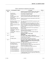
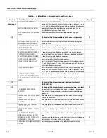
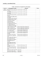
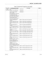
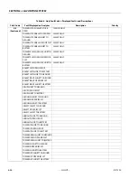
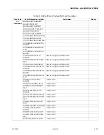
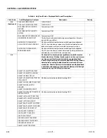
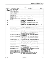
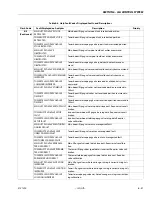
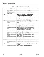
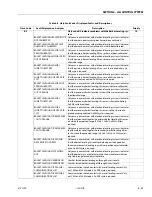
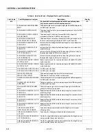
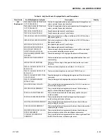
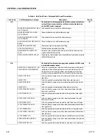
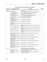
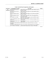
Table 6-6. Help Fault Codes, Displayed Faults, and Descriptions
Flash Code
Fault Displayed on Analyzer
Description
Priority
Содержание 450A II Series
Страница 21: ...SECTION 1 SPECIFICATIONS 3121290 JLG Lift 1 5 Figure 1 2 Operator Maintenance and Lubrication Diagram ...
Страница 44: ...SECTION 3 CHASSIS TURNTABLE 3 4 JLG Lift 3121290 Figure 3 3 Drive Hub and Brake Assembly 2WD and 4WD ...
Страница 46: ...SECTION 3 CHASSIS TURNTABLE 3 6 JLG Lift 3121290 Figure 3 4 Drive Hub 4WD Front Only ...
Страница 79: ...SECTION 3 CHASSIS TURNTABLE 3121290 JLG Lift 3 39 Figure 3 32 Swing Bearing Drive ...
Страница 101: ...SECTION 3 CHASSIS TURNTABLE 3121290 JLG Lift 3 61 Figure 3 42 Auxiliary Pump ...
Страница 107: ...SECTION 3 CHASSIS TURNTABLE 3121290 JLG Lift 3 67 Figure 3 47 Deutz EMR 2 Troubleshooting Flow Chart ...
Страница 108: ...SECTION 3 CHASSIS TURNTABLE 3 68 JLG Lift 3121290 Figure 3 48 Deutz EMR 2 Vehicle Side Connection Diagram ...
Страница 109: ...SECTION 3 CHASSIS TURNTABLE 3121290 JLG Lift 3 69 Figure 3 49 Deutz EMR 2 Engine Side Connection Diagram Sheet 1 of 2 ...
Страница 110: ...SECTION 3 CHASSIS TURNTABLE 3 70 JLG Lift 3121290 Figure 3 50 Deutz EMR 2 Engine Side Connection Diagram Sheet 2 of 2 ...
Страница 111: ...SECTION 3 CHASSIS TURNTABLE 3121290 JLG Lift 3 71 Figure 3 51 EMR 2 Engine Plug Pin Identification ...
Страница 112: ...SECTION 3 CHASSIS TURNTABLE 3 72 JLG Lift 3121290 Figure 3 52 EMR 2 Vehicle Plug Pin Identification ...
Страница 113: ...SECTION 3 CHASSIS TURNTABLE 3121290 JLG Lift 3 73 Figure 3 53 EMR2 Fault Codes Sheet 1 of 5 ...
Страница 114: ...SECTION 3 CHASSIS TURNTABLE 3 74 JLG Lift 3121290 Figure 3 54 EMR2 Fault Codes Sheet 2 of 5 ...
Страница 115: ...SECTION 3 CHASSIS TURNTABLE 3121290 JLG Lift 3 75 Figure 3 55 EMR2 Fault Codes Sheet 3 of 5 ...
Страница 116: ...SECTION 3 CHASSIS TURNTABLE 3 76 JLG Lift 3121290 Figure 3 56 EMR2 Fault Codes Sheet 4 of 5 ...
Страница 117: ...SECTION 3 CHASSIS TURNTABLE 3121290 JLG Lift 3 77 Figure 3 57 EMR2 Fault Codes Sheet 5 of 5 ...
Страница 159: ...SECTION 3 CHASSIS TURNTABLE 3121290 JLG Lift 3 119 ...
Страница 161: ...SECTION 3 CHASSIS TURNTABLE 3121290 JLG Lift 3 121 ...
Страница 163: ...SECTION 3 CHASSIS TURNTABLE 3121290 JLG Lift 3 123 ...
Страница 165: ...SECTION 3 CHASSIS TURNTABLE 3121290 JLG Lift 3 125 ...
Страница 173: ...SECTION 3 CHASSIS TURNTABLE 3121290 JLG Lift 3 133 Sensor Transducer Type ...
Страница 177: ...SECTION 3 CHASSIS TURNTABLE 3121290 JLG Lift 3 137 Sensor Transducer Type ...
Страница 179: ...SECTION 3 CHASSIS TURNTABLE 3121290 JLG Lift 3 139 ...
Страница 181: ...SECTION 3 CHASSIS TURNTABLE 3121290 JLG Lift 3 141 ...
Страница 183: ...SECTION 3 CHASSIS TURNTABLE 3121290 JLG Lift 3 143 ...
Страница 185: ...SECTION 3 CHASSIS TURNTABLE 3121290 JLG Lift 3 145 ...
Страница 187: ...SECTION 3 CHASSIS TURNTABLE 3121290 JLG Lift 3 147 ...
Страница 203: ...SECTION 3 CHASSIS TURNTABLE 3121290 JLG Lift 3 163 ...
Страница 207: ...SECTION 3 CHASSIS TURNTABLE 3121290 JLG Lift 3 167 ...
Страница 217: ...SECTION 4 BOOM PLATFORM 3121290 JLG Lift 4 5 Figure 4 2 Boom Limit Switches ...
Страница 310: ...SECTION 5 HYDRAULICS 5 70 JLG Lift 3121290 NOTES ...
Страница 312: ...SECTION 6 JLG CONTROL SYSTEM 6 2 JLG Lift 3121290 Figure 6 2 Controller Block Diagram 0 ...
Страница 337: ...SECTION 6 JLG CONTROL SYSTEM 3121290 JLG Lift 6 27 Figure 6 11 System Test Flow Chart Platform Tests ...
Страница 339: ...SECTION 6 JLG CONTROL SYSTEM 3121290 JLG Lift 6 29 Figure 6 12 System Test Flow Chart Ground Station Tests ...
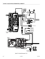
Страница 350: ...SECTION 6 JLG CONTROL SYSTEM 6 40 JLG Lift 3121290 Figure 6 13 Control Module And Fault Code Light Locations ...
Страница 370: ...SECTION 6 JLG CONTROL SYSTEM 6 60 JLG Lift 3121290 NOTES ...
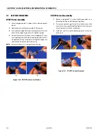
Страница 380: ...SECTION 7 BASIC ELECTRICAL INFORMATION SCHEMATICS 7 10 JLG Lift 3121290 Figure 7 26 Electrical Components 1 of 2 ...
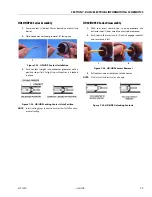
Страница 381: ...SECTION 7 BASIC ELECTRICAL INFORMATION SCHEMATICS 3121290 JLG Lift 7 11 Figure 7 27 Electrical Components 2 of 2 ...
Страница 388: ...SECTION 7 BASIC ELECTRICAL INFORMATION SCHEMATICS 7 18 JLG Lift 3121290 Figure 7 34 Main Hydraulic Schematic 1 of 2 ...
Страница 394: ...SECTION 7 BASIC ELECTRICAL INFORMATION SCHEMATICS 7 24 JLG Lift 3121290 NOTES ...
Страница 395: ......