
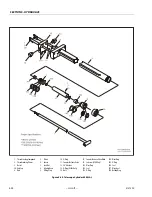

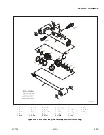

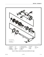


SECTION 5 - HYDRAULICS
3121290
– JLG Lift –
5-25
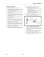
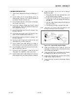
CLEANING AND INSPECTION
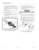
1.
Clean all parts thoroughly with approved cleaning sol-
vent.
2.
Inspect cylinder rod for scoring, tapering, ovality, or
other damage. If necessary, dress rod with Scotch Brite
or equivalent. Replace rod if necessary.
3.
Inspect threaded portion of rod for excessive damage.
Dress threads as necessary.
4.
Inspect inner surface of cylinder barrel tube for scoring
or other damage. Check inside diameter for tapering or
ovality. Replace if necessary.
5.
Inspect threaded portion of barrel for damage. Dress
threads as necessary.
6.
Inspect piston for damage, scoring, and distortion. Dress
piston surface or replace piston as necessary.
7.
Inspect threaded portion of piston for damage. Dress
threads as necessary.
8.
Inspect seal and O-ring grooves in piston for burrs and
sharp edges. Dress surfaces as necessary.
9.
Inspect cylinder head inside diameter for scoring or
other damage, ovality, and tapering. Replace as needed.
10.
Inspect threaded portion of head and end cap for dam-
age. Dress threads as necessary.
11.
Inspect seal and O-ring grooves in head for burrs and
sharp edges. Dress applicable surfaces as necessary.
12.
Inspect cylinder head outside diameter for scoring or
other damage, ovality, and tapering. Replace as needed.
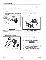
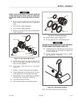
13.
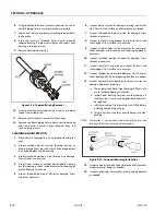
Inspect rod bearings for excessive wear or damage.
Replace as needed.
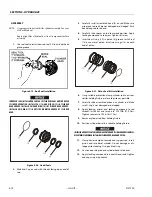
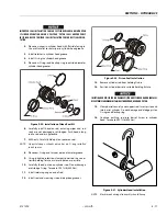
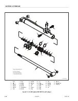
a. Thoroughly clean hole, (steel bushing) of burrs, dirt
etc. to facilitate bearing installation.
b. Inspect steel bushing for wear or other damage. If
steel bushing is worn or damaged, rod/barrel must
be replaced.
c. Lubricate inside of steel bushing with WD40 prior to
bearing installation.
d. Press bearing in bushing using correct size arbor.
NOTE:
Lubrication is not required with nickel plated pins and
bearings. Install pin in composite bushing dry.
Figure 5-46. Composite Bushing Installation
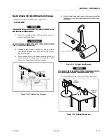
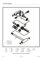
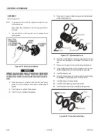
14.
Inspect travel limiting collar or spacer for burrs and
sharp edges. If necessary, dress inside diameter surface
with Scotch Brite or equivalent.
15.
Inspect port block fittings and holding valves. Replace
as needed. Torque valves 30-35 ft-lb (41-48 Nm).
16.
Inspect oil ports for blockage or presence of dirt or other
foreign material. Repair as necessary.
17.
Inspect piston rings for cracks or other damage. Replace
as needed.
Содержание 450A II Series
Страница 21: ...SECTION 1 SPECIFICATIONS 3121290 JLG Lift 1 5 Figure 1 2 Operator Maintenance and Lubrication Diagram ...
Страница 44: ...SECTION 3 CHASSIS TURNTABLE 3 4 JLG Lift 3121290 Figure 3 3 Drive Hub and Brake Assembly 2WD and 4WD ...
Страница 46: ...SECTION 3 CHASSIS TURNTABLE 3 6 JLG Lift 3121290 Figure 3 4 Drive Hub 4WD Front Only ...
Страница 79: ...SECTION 3 CHASSIS TURNTABLE 3121290 JLG Lift 3 39 Figure 3 32 Swing Bearing Drive ...
Страница 101: ...SECTION 3 CHASSIS TURNTABLE 3121290 JLG Lift 3 61 Figure 3 42 Auxiliary Pump ...
Страница 107: ...SECTION 3 CHASSIS TURNTABLE 3121290 JLG Lift 3 67 Figure 3 47 Deutz EMR 2 Troubleshooting Flow Chart ...
Страница 108: ...SECTION 3 CHASSIS TURNTABLE 3 68 JLG Lift 3121290 Figure 3 48 Deutz EMR 2 Vehicle Side Connection Diagram ...
Страница 109: ...SECTION 3 CHASSIS TURNTABLE 3121290 JLG Lift 3 69 Figure 3 49 Deutz EMR 2 Engine Side Connection Diagram Sheet 1 of 2 ...
Страница 110: ...SECTION 3 CHASSIS TURNTABLE 3 70 JLG Lift 3121290 Figure 3 50 Deutz EMR 2 Engine Side Connection Diagram Sheet 2 of 2 ...
Страница 111: ...SECTION 3 CHASSIS TURNTABLE 3121290 JLG Lift 3 71 Figure 3 51 EMR 2 Engine Plug Pin Identification ...
Страница 112: ...SECTION 3 CHASSIS TURNTABLE 3 72 JLG Lift 3121290 Figure 3 52 EMR 2 Vehicle Plug Pin Identification ...
Страница 113: ...SECTION 3 CHASSIS TURNTABLE 3121290 JLG Lift 3 73 Figure 3 53 EMR2 Fault Codes Sheet 1 of 5 ...
Страница 114: ...SECTION 3 CHASSIS TURNTABLE 3 74 JLG Lift 3121290 Figure 3 54 EMR2 Fault Codes Sheet 2 of 5 ...
Страница 115: ...SECTION 3 CHASSIS TURNTABLE 3121290 JLG Lift 3 75 Figure 3 55 EMR2 Fault Codes Sheet 3 of 5 ...
Страница 116: ...SECTION 3 CHASSIS TURNTABLE 3 76 JLG Lift 3121290 Figure 3 56 EMR2 Fault Codes Sheet 4 of 5 ...
Страница 117: ...SECTION 3 CHASSIS TURNTABLE 3121290 JLG Lift 3 77 Figure 3 57 EMR2 Fault Codes Sheet 5 of 5 ...
Страница 159: ...SECTION 3 CHASSIS TURNTABLE 3121290 JLG Lift 3 119 ...
Страница 161: ...SECTION 3 CHASSIS TURNTABLE 3121290 JLG Lift 3 121 ...
Страница 163: ...SECTION 3 CHASSIS TURNTABLE 3121290 JLG Lift 3 123 ...
Страница 165: ...SECTION 3 CHASSIS TURNTABLE 3121290 JLG Lift 3 125 ...
Страница 173: ...SECTION 3 CHASSIS TURNTABLE 3121290 JLG Lift 3 133 Sensor Transducer Type ...
Страница 177: ...SECTION 3 CHASSIS TURNTABLE 3121290 JLG Lift 3 137 Sensor Transducer Type ...
Страница 179: ...SECTION 3 CHASSIS TURNTABLE 3121290 JLG Lift 3 139 ...
Страница 181: ...SECTION 3 CHASSIS TURNTABLE 3121290 JLG Lift 3 141 ...
Страница 183: ...SECTION 3 CHASSIS TURNTABLE 3121290 JLG Lift 3 143 ...
Страница 185: ...SECTION 3 CHASSIS TURNTABLE 3121290 JLG Lift 3 145 ...
Страница 187: ...SECTION 3 CHASSIS TURNTABLE 3121290 JLG Lift 3 147 ...
Страница 203: ...SECTION 3 CHASSIS TURNTABLE 3121290 JLG Lift 3 163 ...
Страница 207: ...SECTION 3 CHASSIS TURNTABLE 3121290 JLG Lift 3 167 ...
Страница 217: ...SECTION 4 BOOM PLATFORM 3121290 JLG Lift 4 5 Figure 4 2 Boom Limit Switches ...
Страница 310: ...SECTION 5 HYDRAULICS 5 70 JLG Lift 3121290 NOTES ...
Страница 312: ...SECTION 6 JLG CONTROL SYSTEM 6 2 JLG Lift 3121290 Figure 6 2 Controller Block Diagram 0 ...
Страница 337: ...SECTION 6 JLG CONTROL SYSTEM 3121290 JLG Lift 6 27 Figure 6 11 System Test Flow Chart Platform Tests ...
Страница 339: ...SECTION 6 JLG CONTROL SYSTEM 3121290 JLG Lift 6 29 Figure 6 12 System Test Flow Chart Ground Station Tests ...
Страница 350: ...SECTION 6 JLG CONTROL SYSTEM 6 40 JLG Lift 3121290 Figure 6 13 Control Module And Fault Code Light Locations ...
Страница 370: ...SECTION 6 JLG CONTROL SYSTEM 6 60 JLG Lift 3121290 NOTES ...
Страница 380: ...SECTION 7 BASIC ELECTRICAL INFORMATION SCHEMATICS 7 10 JLG Lift 3121290 Figure 7 26 Electrical Components 1 of 2 ...
Страница 381: ...SECTION 7 BASIC ELECTRICAL INFORMATION SCHEMATICS 3121290 JLG Lift 7 11 Figure 7 27 Electrical Components 2 of 2 ...
Страница 388: ...SECTION 7 BASIC ELECTRICAL INFORMATION SCHEMATICS 7 18 JLG Lift 3121290 Figure 7 34 Main Hydraulic Schematic 1 of 2 ...
Страница 394: ...SECTION 7 BASIC ELECTRICAL INFORMATION SCHEMATICS 7 24 JLG Lift 3121290 NOTES ...
Страница 395: ......