


SECTION 3 - CHASSIS & TURNTABLE
3-114
– JLG Lift –
3121290
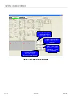
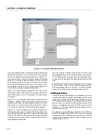
Accessing fault information is accomplished through a double
left-click of the fault LED in the historic fault list. This produces
the Historic Fault Information interface shown in Figure 3-75.
From this interface a user can interpret a diagnostic trouble
code (DTC) message, identify whether or not the fault
occurred during the current key cycle, identify if the fault
caused engine shutdown, determine how many key cycles
have occurred since fault was last active, clear selected or all
historic faults, and view snapshot and flight data.
outlines options displayed in the Historic Fault
Information screen. Historic faults are not overwritten if the
same fault becomes active, storing data from the original
active fault.
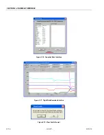
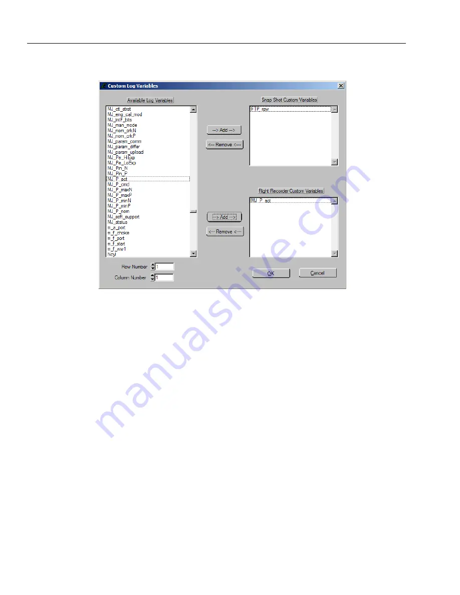
Figure 3-76. is an example of a fault snapshot after View Fault
Snapshot is selected. Data is presented in two columns; base
and custom variables. FSS data may be saved to a PC in text
format with an .fss extension when retrieved. An FSS saved to
a PC may be reviewed in any ASCII based software program.
Figure 3-77. shows the Flight Data Recorder interface after
View Flight Data Recorder is selected. The FDR captures a ten
second (eight seconds prior and two seconds after generating
the fault) strip of data for base and custom variables. FDR data
is presented in an interface similar to the Plot interface for a
quick graphical presentation.
From this interface, FDR data may be saved to the PC in text,
tab-delimited format with an .fdr file extension. Once saved to
PC, FDR data may be reviewed with any graphical post-pro-
cessing software capable of handling tab-delimited format-
ting.
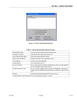
Fault information may be manually erased using the “Clear”
button functions. Once a “Clear” function has been selected,
the dialog prompt shown in
Figure 3-78. will be displayed.
Choosing YES deletes all fault information from the ECM.
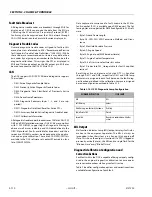
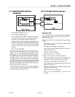
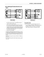
DBW Diagnostic Test
The DGC engine control module uses a diagnostic test to ver-
ify proper drive-by-wire throttle actuator operation. This diag-
nostic test is software selectable through the EDIS using the
ECIPP protocol. The test permits full-authority operation of an
electronic throttle via the throttle command input while
engine is in “Stopped” state only. The ECM reverts to normal
operation if “Off” state is selected, ignition voltage is lost, or
engine speed is sensed.
To enable test, go to DBW page of the EDIS. Set “DBW test
mode” to “Enabled”. Double-click “TPS Command” setting and
enter desired DBW throttle actuator position. The throttle
actuator should move to position entered. To disable test, set
“DBW test mode” to “Off.”
Figure 3-74. Custom Fault Variable Interface
Содержание 450A II Series
Страница 21: ...SECTION 1 SPECIFICATIONS 3121290 JLG Lift 1 5 Figure 1 2 Operator Maintenance and Lubrication Diagram ...
Страница 44: ...SECTION 3 CHASSIS TURNTABLE 3 4 JLG Lift 3121290 Figure 3 3 Drive Hub and Brake Assembly 2WD and 4WD ...
Страница 46: ...SECTION 3 CHASSIS TURNTABLE 3 6 JLG Lift 3121290 Figure 3 4 Drive Hub 4WD Front Only ...
Страница 79: ...SECTION 3 CHASSIS TURNTABLE 3121290 JLG Lift 3 39 Figure 3 32 Swing Bearing Drive ...
Страница 101: ...SECTION 3 CHASSIS TURNTABLE 3121290 JLG Lift 3 61 Figure 3 42 Auxiliary Pump ...
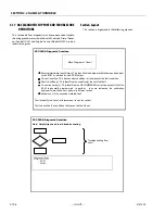
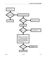
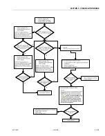
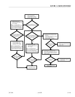
Страница 107: ...SECTION 3 CHASSIS TURNTABLE 3121290 JLG Lift 3 67 Figure 3 47 Deutz EMR 2 Troubleshooting Flow Chart ...
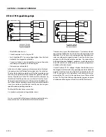
Страница 108: ...SECTION 3 CHASSIS TURNTABLE 3 68 JLG Lift 3121290 Figure 3 48 Deutz EMR 2 Vehicle Side Connection Diagram ...
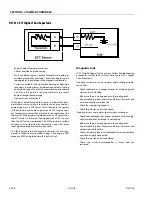
Страница 109: ...SECTION 3 CHASSIS TURNTABLE 3121290 JLG Lift 3 69 Figure 3 49 Deutz EMR 2 Engine Side Connection Diagram Sheet 1 of 2 ...
Страница 110: ...SECTION 3 CHASSIS TURNTABLE 3 70 JLG Lift 3121290 Figure 3 50 Deutz EMR 2 Engine Side Connection Diagram Sheet 2 of 2 ...
Страница 111: ...SECTION 3 CHASSIS TURNTABLE 3121290 JLG Lift 3 71 Figure 3 51 EMR 2 Engine Plug Pin Identification ...
Страница 112: ...SECTION 3 CHASSIS TURNTABLE 3 72 JLG Lift 3121290 Figure 3 52 EMR 2 Vehicle Plug Pin Identification ...
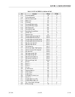
Страница 113: ...SECTION 3 CHASSIS TURNTABLE 3121290 JLG Lift 3 73 Figure 3 53 EMR2 Fault Codes Sheet 1 of 5 ...
Страница 114: ...SECTION 3 CHASSIS TURNTABLE 3 74 JLG Lift 3121290 Figure 3 54 EMR2 Fault Codes Sheet 2 of 5 ...
Страница 115: ...SECTION 3 CHASSIS TURNTABLE 3121290 JLG Lift 3 75 Figure 3 55 EMR2 Fault Codes Sheet 3 of 5 ...
Страница 116: ...SECTION 3 CHASSIS TURNTABLE 3 76 JLG Lift 3121290 Figure 3 56 EMR2 Fault Codes Sheet 4 of 5 ...
Страница 117: ...SECTION 3 CHASSIS TURNTABLE 3121290 JLG Lift 3 77 Figure 3 57 EMR2 Fault Codes Sheet 5 of 5 ...
Страница 159: ...SECTION 3 CHASSIS TURNTABLE 3121290 JLG Lift 3 119 ...
Страница 161: ...SECTION 3 CHASSIS TURNTABLE 3121290 JLG Lift 3 121 ...
Страница 163: ...SECTION 3 CHASSIS TURNTABLE 3121290 JLG Lift 3 123 ...
Страница 165: ...SECTION 3 CHASSIS TURNTABLE 3121290 JLG Lift 3 125 ...
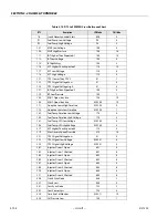
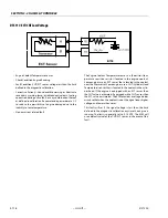
Страница 173: ...SECTION 3 CHASSIS TURNTABLE 3121290 JLG Lift 3 133 Sensor Transducer Type ...
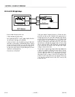
Страница 177: ...SECTION 3 CHASSIS TURNTABLE 3121290 JLG Lift 3 137 Sensor Transducer Type ...
Страница 179: ...SECTION 3 CHASSIS TURNTABLE 3121290 JLG Lift 3 139 ...
Страница 181: ...SECTION 3 CHASSIS TURNTABLE 3121290 JLG Lift 3 141 ...
Страница 183: ...SECTION 3 CHASSIS TURNTABLE 3121290 JLG Lift 3 143 ...
Страница 185: ...SECTION 3 CHASSIS TURNTABLE 3121290 JLG Lift 3 145 ...
Страница 187: ...SECTION 3 CHASSIS TURNTABLE 3121290 JLG Lift 3 147 ...
Страница 203: ...SECTION 3 CHASSIS TURNTABLE 3121290 JLG Lift 3 163 ...
Страница 207: ...SECTION 3 CHASSIS TURNTABLE 3121290 JLG Lift 3 167 ...
Страница 217: ...SECTION 4 BOOM PLATFORM 3121290 JLG Lift 4 5 Figure 4 2 Boom Limit Switches ...
Страница 310: ...SECTION 5 HYDRAULICS 5 70 JLG Lift 3121290 NOTES ...
Страница 312: ...SECTION 6 JLG CONTROL SYSTEM 6 2 JLG Lift 3121290 Figure 6 2 Controller Block Diagram 0 ...
Страница 337: ...SECTION 6 JLG CONTROL SYSTEM 3121290 JLG Lift 6 27 Figure 6 11 System Test Flow Chart Platform Tests ...
Страница 339: ...SECTION 6 JLG CONTROL SYSTEM 3121290 JLG Lift 6 29 Figure 6 12 System Test Flow Chart Ground Station Tests ...
Страница 350: ...SECTION 6 JLG CONTROL SYSTEM 6 40 JLG Lift 3121290 Figure 6 13 Control Module And Fault Code Light Locations ...
Страница 370: ...SECTION 6 JLG CONTROL SYSTEM 6 60 JLG Lift 3121290 NOTES ...
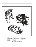
Страница 380: ...SECTION 7 BASIC ELECTRICAL INFORMATION SCHEMATICS 7 10 JLG Lift 3121290 Figure 7 26 Electrical Components 1 of 2 ...
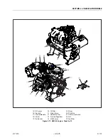
Страница 381: ...SECTION 7 BASIC ELECTRICAL INFORMATION SCHEMATICS 3121290 JLG Lift 7 11 Figure 7 27 Electrical Components 2 of 2 ...
Страница 388: ...SECTION 7 BASIC ELECTRICAL INFORMATION SCHEMATICS 7 18 JLG Lift 3121290 Figure 7 34 Main Hydraulic Schematic 1 of 2 ...
Страница 394: ...SECTION 7 BASIC ELECTRICAL INFORMATION SCHEMATICS 7 24 JLG Lift 3121290 NOTES ...
Страница 395: ......