


SECTION 3 - CHASSIS & TURNTABLE
3-148
– JLG Lift –
3121290
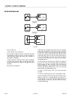
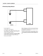
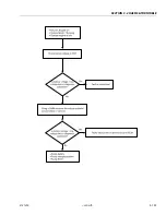
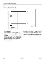
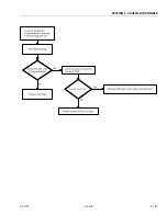
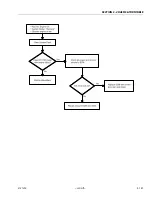
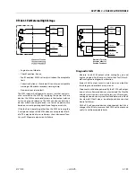
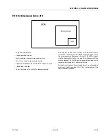
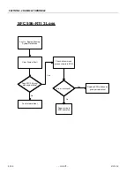
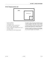
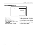
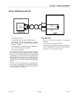
DTC 642- 5 Volt External Low Voltage
• Engine Control Module.
• Check Condition- Key on.
• Fault Condition- ECM 5-volt output is below the acceptable
limit.
• Corrective Action(s)- Illuminate MIL and/or sound audible
warning or illuminate secondary warning lamp.
• Non-emissions related fault.
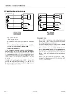
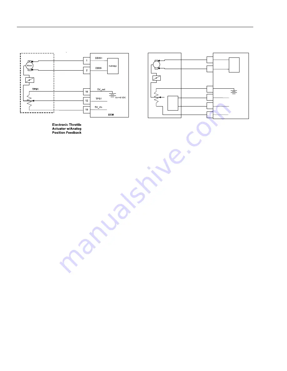
The ECM supplies 5-volt power to sensors, switches, and actu-
ators external to the ECM. By supplying the power to these
devices, the ECM can accurately measure their output relative
to its own ground reference. The ECM can also control when
the devices are active and put the devices in a low or no power
state based on the current operating condition of the engine
or vehicle.
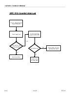
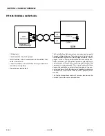
If this fault sets, something other than the ECM is drawing ECM
5-volt power output below an acceptable threshold. This may
be due to a short in wire harness, malfunctioning device, or
ECM power output circuitry failure.
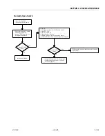
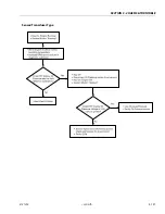
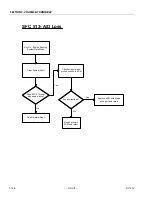
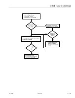
Diagnostic Aids
• Measure ECM 5-volt output while cycling key on with
engine stopped. Verify output is lower than fault thresh-
olds configured in diagnostic calibration.
• Inspect 5-Volt output circuit in wire harness and look for
shorts to ground or other harness circuits.
• Disconnect each device powered by the ECM 5-volt output
one-at-a-time. Powered devices may include throttle actu-
ator, smart sensors, smart actuators, etc. After disconnect-
ing device, observe system fault and determine if fault has
cleared. If fault clears, troubleshoot disconnected device
for failures.
• With all 5-volt powered devices disconnected, look for a
change in fault state and measure ECM 5-volt output. Verify
it is within acceptable limits.
E
le
c
tro
n
ic
T
h
ro
ttle
A
c
tua
to
r w
/S
e
ria
l
P
o
s
itio
n
F
e
e
d
b
a
c
k
2
1
6
1
3
1
2
1
5
V
_
e
x
t
V
s
=
+
5
V
D
C
5
V
_
rtn
T
P
S
1
T
P
S
S
E
R
+
+
-M
o
to
r
D
B
W
-
D
B
W
+
E
C
M
H
-B
rid
g
e
1
9
T
P
S
S
E
R
-
S
e
ria
l
x
m
itte
r
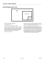
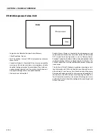
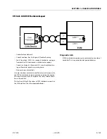
Electronic Throttle
Actuator w/Serial
Position Feedback
2
16
13
12
1
5V_ext
Vs=+5 VDC
5V_rtn
TPS1
TPS SER +
+
-
Motor
DBW-
DBW+
ECM
H-Bridge
19
TPS SER -
Serial
xmitter
Содержание 450A II Series
Страница 21: ...SECTION 1 SPECIFICATIONS 3121290 JLG Lift 1 5 Figure 1 2 Operator Maintenance and Lubrication Diagram ...
Страница 44: ...SECTION 3 CHASSIS TURNTABLE 3 4 JLG Lift 3121290 Figure 3 3 Drive Hub and Brake Assembly 2WD and 4WD ...
Страница 46: ...SECTION 3 CHASSIS TURNTABLE 3 6 JLG Lift 3121290 Figure 3 4 Drive Hub 4WD Front Only ...
Страница 79: ...SECTION 3 CHASSIS TURNTABLE 3121290 JLG Lift 3 39 Figure 3 32 Swing Bearing Drive ...
Страница 101: ...SECTION 3 CHASSIS TURNTABLE 3121290 JLG Lift 3 61 Figure 3 42 Auxiliary Pump ...
Страница 107: ...SECTION 3 CHASSIS TURNTABLE 3121290 JLG Lift 3 67 Figure 3 47 Deutz EMR 2 Troubleshooting Flow Chart ...
Страница 108: ...SECTION 3 CHASSIS TURNTABLE 3 68 JLG Lift 3121290 Figure 3 48 Deutz EMR 2 Vehicle Side Connection Diagram ...
Страница 109: ...SECTION 3 CHASSIS TURNTABLE 3121290 JLG Lift 3 69 Figure 3 49 Deutz EMR 2 Engine Side Connection Diagram Sheet 1 of 2 ...
Страница 110: ...SECTION 3 CHASSIS TURNTABLE 3 70 JLG Lift 3121290 Figure 3 50 Deutz EMR 2 Engine Side Connection Diagram Sheet 2 of 2 ...
Страница 111: ...SECTION 3 CHASSIS TURNTABLE 3121290 JLG Lift 3 71 Figure 3 51 EMR 2 Engine Plug Pin Identification ...
Страница 112: ...SECTION 3 CHASSIS TURNTABLE 3 72 JLG Lift 3121290 Figure 3 52 EMR 2 Vehicle Plug Pin Identification ...
Страница 113: ...SECTION 3 CHASSIS TURNTABLE 3121290 JLG Lift 3 73 Figure 3 53 EMR2 Fault Codes Sheet 1 of 5 ...
Страница 114: ...SECTION 3 CHASSIS TURNTABLE 3 74 JLG Lift 3121290 Figure 3 54 EMR2 Fault Codes Sheet 2 of 5 ...
Страница 115: ...SECTION 3 CHASSIS TURNTABLE 3121290 JLG Lift 3 75 Figure 3 55 EMR2 Fault Codes Sheet 3 of 5 ...
Страница 116: ...SECTION 3 CHASSIS TURNTABLE 3 76 JLG Lift 3121290 Figure 3 56 EMR2 Fault Codes Sheet 4 of 5 ...
Страница 117: ...SECTION 3 CHASSIS TURNTABLE 3121290 JLG Lift 3 77 Figure 3 57 EMR2 Fault Codes Sheet 5 of 5 ...
Страница 159: ...SECTION 3 CHASSIS TURNTABLE 3121290 JLG Lift 3 119 ...
Страница 161: ...SECTION 3 CHASSIS TURNTABLE 3121290 JLG Lift 3 121 ...
Страница 163: ...SECTION 3 CHASSIS TURNTABLE 3121290 JLG Lift 3 123 ...
Страница 165: ...SECTION 3 CHASSIS TURNTABLE 3121290 JLG Lift 3 125 ...
Страница 173: ...SECTION 3 CHASSIS TURNTABLE 3121290 JLG Lift 3 133 Sensor Transducer Type ...
Страница 177: ...SECTION 3 CHASSIS TURNTABLE 3121290 JLG Lift 3 137 Sensor Transducer Type ...
Страница 179: ...SECTION 3 CHASSIS TURNTABLE 3121290 JLG Lift 3 139 ...
Страница 181: ...SECTION 3 CHASSIS TURNTABLE 3121290 JLG Lift 3 141 ...
Страница 183: ...SECTION 3 CHASSIS TURNTABLE 3121290 JLG Lift 3 143 ...
Страница 185: ...SECTION 3 CHASSIS TURNTABLE 3121290 JLG Lift 3 145 ...
Страница 187: ...SECTION 3 CHASSIS TURNTABLE 3121290 JLG Lift 3 147 ...
Страница 203: ...SECTION 3 CHASSIS TURNTABLE 3121290 JLG Lift 3 163 ...
Страница 207: ...SECTION 3 CHASSIS TURNTABLE 3121290 JLG Lift 3 167 ...
Страница 217: ...SECTION 4 BOOM PLATFORM 3121290 JLG Lift 4 5 Figure 4 2 Boom Limit Switches ...
Страница 310: ...SECTION 5 HYDRAULICS 5 70 JLG Lift 3121290 NOTES ...
Страница 312: ...SECTION 6 JLG CONTROL SYSTEM 6 2 JLG Lift 3121290 Figure 6 2 Controller Block Diagram 0 ...
Страница 337: ...SECTION 6 JLG CONTROL SYSTEM 3121290 JLG Lift 6 27 Figure 6 11 System Test Flow Chart Platform Tests ...
Страница 339: ...SECTION 6 JLG CONTROL SYSTEM 3121290 JLG Lift 6 29 Figure 6 12 System Test Flow Chart Ground Station Tests ...
Страница 350: ...SECTION 6 JLG CONTROL SYSTEM 6 40 JLG Lift 3121290 Figure 6 13 Control Module And Fault Code Light Locations ...
Страница 370: ...SECTION 6 JLG CONTROL SYSTEM 6 60 JLG Lift 3121290 NOTES ...
Страница 380: ...SECTION 7 BASIC ELECTRICAL INFORMATION SCHEMATICS 7 10 JLG Lift 3121290 Figure 7 26 Electrical Components 1 of 2 ...
Страница 381: ...SECTION 7 BASIC ELECTRICAL INFORMATION SCHEMATICS 3121290 JLG Lift 7 11 Figure 7 27 Electrical Components 2 of 2 ...
Страница 388: ...SECTION 7 BASIC ELECTRICAL INFORMATION SCHEMATICS 7 18 JLG Lift 3121290 Figure 7 34 Main Hydraulic Schematic 1 of 2 ...
Страница 394: ...SECTION 7 BASIC ELECTRICAL INFORMATION SCHEMATICS 7 24 JLG Lift 3121290 NOTES ...
Страница 395: ......