SECTION 2 - PROCEDURES
2-16
– JLG Lift –
3121804
10.
Carefully install one of the cylinder heads on one
end of the cylinder rod and push the head onto the
rod until it is snug against the end of the cylinder
barrel.
11.
Install one of the cylinder head retainers on the end
of the cylinder barrel and tighten with a suitable
chain wrench.
12.
Carefully install the remaining cylinder head on the
opposite end of the cylinder rod and push the head
onto the rod until it is snug against the end of the
cylinder barrel.
13.
Install the remaining cylinder head retainer on the
end of the cylinder barrel and tighten with a suitable
chain wrench.
Installation
1.
Carefully install the steer cylinder assembly into the
front axle. Align the cylinder mounting block on the
barrel with the mounting slot in the bottom of the
axle and lower the steer cylinder until the mounting
block rests in the slot.
2.
Turn the steer wheels to line up the mounting holes
in the steer spindles and the steer cylinder ends.
Secure each end of the steer cylinder with a bolt and
lock nut.
3.
Reconnect the hydraulic hoses to the applicable cyl-
inder ports.
2.12 OSCILLATION CYLINDER BLEEDING
NOTE: Park the machine on a firm and level surface with the
rear wheels blocked before starting the bleeding pro-
cedure.
1.
Jack up the front of the machine so that both wheels
are raised enough to allow the axle to fully oscillate.
2.
Have a second person start the engine, press and
hold the start button until Hi engine is activated.
3.
On the side of the axle that is fully raised, loosen the
bleeder screw to release any air that may be in the
hydraulic line. Continue to bleed until no air bubbles
are visible.
4.
Tighten the bleeder screw then push the raised
wheel down and repeat the process for the opposite
level cylinder.
2.13 MAGNETIC SPEED PICKUP CLEANING
PROCEDURE
1.
Locate the magnetic speed pickup on the bell hous-
ing on the right side of the motor.
2.
Using an 11/16 wrench, loosen the jam nut and,
using your fingers, thread the pickup out of the bell
housing.
3.
After cleaning and inspecting the magnetic speed
pickup reinstall back into the bell housing.
4.
The magnetic speed pickup should be tightened fin-
ger tight and then backed out 1/4 turn to properly
set.
NOTE: Flats on the magnetic pickup must be oriented verti-
cally.
5.
Replace the jam nut and tighten.
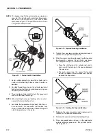
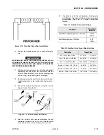
Figure 2-17. Magnetic Speed Pickup
Figure 2-18. Magnetic Speed Pickup Removal
Содержание 330CRT
Страница 1: ...Service Maintenance Manual Model 330CRT 400CRT 3121804 April 7 2004 ...
Страница 2: ......
Страница 8: ...TABLE OF CONTENTS iv JLG Lift 3121804 This page left blank intentionally ...
Страница 12: ...SECTION 1 SPECIFICATIONS 1 4 JLG Lift 3121804 Figure 1 1 Torque Chart ...
Страница 20: ...SECTION 2 PROCEDURES 2 6 JLG Lift 3121804 Figure 2 1 Arms and Platform Positioning and Support Cylinder Repair ...
Страница 22: ...SECTION 2 PROCEDURES 2 8 JLG Lift 3121804 Figure 2 3 400CRT LIft Cylinder ...
Страница 54: ...SECTION 3 TROUBLESHOOTING 3 12 JLG Lift 3121804 Figure 3 3 Hydraulic Schematic Sheet 1 of 2 ...
Страница 55: ...SECTION 3 TROUBLESHOOTING 3121804 JLG Lift 3 13 2792397 E Figure 3 4 Hydraulic Schematic Sheet 2 of 2 ...
Страница 56: ...SECTION 3 TROUBLESHOOTING 3 14 JLG Lift 3121804 This page intentionally left blank ...
Страница 57: ......

