


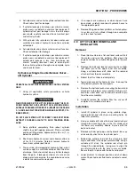


SECTION 1 - SPECIFICATIONS
3121804
– JLG Lift –
1-3
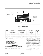
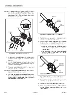
H[WHQGVIURP
IURQWRIPDFKLQH
1
2
3
1RWH
+UV PRQWKV
+UV PRQWKV
+UV \HDU
+UV \HDUV
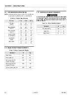
Table 1-3. Lubrication Chart
INDEX
NO
COMPONENT
NUMBER/TYPE LUBE POINTS
LUBE METHOD
INTERVAL
HOURS
1
Hydraulic Oil Reservoir
Fill Cap/Drain Plug
HO - Check HO Level
HO - Change HO
10/500
2
Hydraulic Filter Element
N/A
Initial Change - 50 Hours
250
3
Rail Slides
N/A
MPG - Brush
100
4
Engine Crankcase
Fill Cap/Drain Plug
Check Engine Oil Level
10/100
5
*Slide Blocks
Upper and Lower
MPG
100
*
Item 5 not shown on illustration. Item 5 pertains to items
throughout the machine.
KEY TO LUBRICANTS:
MPG - Multi-purpose Grease
EPGL - Extreme Pressure Gear Lube
HO - Hydraulic Oil (Mobil 424)
TO AVOID PERSONAL INJURY, USE SAFETY PROP FOR ALL
MAINTENANCE REQUIRING PLATFORM TO BE ELEVATED.
NOTE: Be sure to lubricate like items on each side
NOTE: Recommended lubricating intervals are based on
machine operations under normal conditions. For
machines used in multi-shift operations and/or
exposed to hostile environments or conditions, lubri-
cation frequencies must be increased accordingly.
Operate hydraulic functions through one complete
cycle before checking hydraulic oil level in tank. Oil
should be visible in ADD sight window on hydraulic
tank. If oil is not visible, add oil until oil is visible in
both ADD and FULL sight windows on tank. Do not
overfill tank.
Any time the pump coupling is removed, coat
splines of coupling with Texaco Code 1912 grease
prior to assembly.
Figure 1-1. Lubrication Diagram
Содержание 330CRT
Страница 1: ...Service Maintenance Manual Model 330CRT 400CRT 3121804 April 7 2004 ...
Страница 2: ......
Страница 8: ...TABLE OF CONTENTS iv JLG Lift 3121804 This page left blank intentionally ...
Страница 12: ...SECTION 1 SPECIFICATIONS 1 4 JLG Lift 3121804 Figure 1 1 Torque Chart ...
Страница 20: ...SECTION 2 PROCEDURES 2 6 JLG Lift 3121804 Figure 2 1 Arms and Platform Positioning and Support Cylinder Repair ...
Страница 22: ...SECTION 2 PROCEDURES 2 8 JLG Lift 3121804 Figure 2 3 400CRT LIft Cylinder ...
Страница 54: ...SECTION 3 TROUBLESHOOTING 3 12 JLG Lift 3121804 Figure 3 3 Hydraulic Schematic Sheet 1 of 2 ...
Страница 55: ...SECTION 3 TROUBLESHOOTING 3121804 JLG Lift 3 13 2792397 E Figure 3 4 Hydraulic Schematic Sheet 2 of 2 ...
Страница 56: ...SECTION 3 TROUBLESHOOTING 3 14 JLG Lift 3121804 This page intentionally left blank ...
Страница 57: ......