background image

9629 Microprocessor Controller

- 21 -

The wire will retract at the retract speed when-

ever the wire stops feeding forward (excepting 

during jog operations).
Take care to set a high enough speed for wire 

retraction, a slow speed will allow the welding 

arc to melt a large ball on the end of the wire as 

it retracts.  This ball (if not removed by cutting 

the wire) will cause problems during the start 

sequence of the next weld.
The retract speed can be set from 0 to 100%.

This is normally the final set-up screen (unless 

the wire feeder is provided with pulse option), 

press and release the power push-button switch 

to switch off the unit.  A second press powers up 

the system into the operator mode.

If the system is fitted with 9629-P pulse option, 

the following screen will appear when the touch 

pad with the down arrow is pressed.

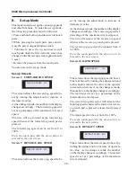
Screen 12 PULSED WIRE FEED

This screen sets up the control for pulsed wire 

feed.  Turning the adjust knob will set wire puls-

ing to  

On 

or  

Off

.  If pulsing is turned to  

Off

no further set-up screens will appear.

Press the touch pad with the down arrow to 

proceed to the next screen.

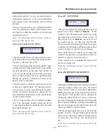
Screen 13 LOW SPEED

This screen allows the speed at which the wire 

feeds during the pulse background time to be 

set.  The speed is set by turning the adjust knob 

to increase or decrease its value.  As the change 

is made, the number on the display changes ac-

cordingly.  The low speed is set as a percentage 

of the maximum wire feed speed.

The low speed should be set to a value high 

enough to avoid a ball being formed on the end 

of the wire during the pulse background time.
The low speed can be set from 5 to 100%.

Press the touch pad with the down arrow to 

proceed to the next screen.

Screen 14 WIRE PULSING

This screen sets the mode in which the wire will 

be pulsed.  Turning the adjust knob will set the 

pulsed mode to 

Timed 

or 

Synch

.

When the wire is set to 

Timed 

mode, the speed 

at which the wire is pulsed is set by specifying 

the peak and background times (see Screens 15 

and 16).  In this mode, pulsing of the wire is 

independent of the power supply, it is therefore 

possible to pulse the wire even if the current is 

not being pulsed.
When the wire is set to Synch mode, the wire 

will pulse synchronously with the pulsing of the 

welding power supply.  For this mode to operate 

satisfactorily, it is necessary for a signal to be 

received by the 9629P control from the power 

supply indicating when the current is at the 

background level.
If the wire pulsing is set to 

Synch

, no further set 

up screens will appear.

Press the touch pad with the down arrow to 

proceed to the next screen.

Screen 15 HIGH PULSE

This screen allows the time during which the 

wire feeds at the programmed wire feed speed 

to be set.  The time is set (in 0.05 second incre-

ments) by turning the adjust knob to increase or 

PULSED WIRE FEED On

LOW SPEED 

25%

WIRE PULSING  Timed

HIGH PULSE 

0.75sec

Содержание 9600 Series

Страница 1: ...alling commissioning or operating this product OPERATION MANUAL for 9629 Microprocessor Controller Jetline Engineering 15 Goodyear Street Irvine CA 92618 Telephone 949 951 1515 Fax 949 951 9237 Web Si...

Страница 2: ...9629 Microprocessor Controller 2...

Страница 3: ...during the warranty period if Jetline s inspection confirms the existence of such defects Jetline s option of repair or replacement will be F O B factory at Irvine California and therefore no compens...

Страница 4: ...you to maintain the equipment in peak condition and achieve maximum efficiency with your welding opera tion Please read these instructions carefully to become aware of every advantage CAUTION Only ex...

Страница 5: ...tions 12 Section IV Description 13 Section V Controls 14 Section VI Modes of Operation 15 A Operator Mode 15 B Set up Mode 20 C Calibration Mode 22 Section VII Operational Sequence 27 Section VIII Mec...

Страница 6: ...9629 Microprocessor Controller 6...

Страница 7: ...talled or improperly grounded equipment is a hazard 1 Do not touch live electrical parts 2 Wear dry hole free insulating gloves and appropriate body protection 3 Disconnect input power before installi...

Страница 8: ...arc to remove welding fumes and gases 3 If ventilation is poor use an approved air supplied respirator 4 Read the Material Safety Data Sheets MSDS and the manufacturer s instruction for metals consum...

Страница 9: ...thin 35 ft 10 7 m of the welding arc If this is not possible tightly cover them with approved covers 4 Be alert that welding sparks and hot materials from welding can easily go through small cracks an...

Страница 10: ...for pacemaker wearers Consult your doctor for complete information I Principal Safety Standards Reference as applicable Safety in Welding and Cutting ANSI Standard Z49 1 from American Welding Society...

Страница 11: ...e control The 9629 control is a microprocessor based control designed and built to provide low cost accurate repeatable control of the wire feed motor It is available in two versions 9629 This control...

Страница 12: ...d to provide slope up of the wire feed speed for hot wire welding 9629 R1 This option can be added to allow remote control of the wire feed speed Processor Intel 80C196KC 20 MHz Display 2 x 20 Backlit...

Страница 13: ...e 9629 control has been designed to be easy to use Its operation is made easier by the use of the display which guides you through the setup process and during the welding sequence tells you what is h...

Страница 14: ...touch pads they are capable of providing two more functions POWER UP DOWN ADJUST REV FOR Rapid Jog This is achieved by pressing the forward or reverse touch pad for a short time releasing it and then...

Страница 15: ...reen 30 If it is desired to change the speed this is done by turning the adjust knob to increase or de crease the speed as necessary As the change is made the number on the display changes accordingly...

Страница 16: ...nd travel at the wire retraction speed defined in the set up mode See Screen 11 for the length of time set in this screen The time can be set by turning the adjust knob to increase or decrease its val...

Страница 17: ...ed The message remains on the screen until the value of the parameter is reduced below the limit This message also appears during welding if the upper limit of wire feed speed is reached in this case...

Страница 18: ...setup mode of operation of the 9629 control see Screen 10 Wire feed will continue at rapid speed as long as the touch pad is pressed The message will remain on the screen as long as wire is feeding at...

Страница 19: ...me the wire starts to feed at the pre programmed wire feed speed Sensing delay After the start delay has timed out this message will be displayed providing that the Closed Loop Mode is On Screen 17 Th...

Страница 20: ...be set by turning the adjust knob to increase or decrease its value As the change is made the number on the display changes accordingly The reverse jog speed is a percentage of the maximum wire feed s...

Страница 21: ...r on the display changes ac cordingly The low speed is set as a percentage of the maximum wire feed speed The low speed should be set to a value high enough to avoid a ball being formed on the end of...

Страница 22: ...629 control into the calibra tion mode Calibration Screens Screen 17 CLOSED LOOP MODE This screen allows the closed loop mode to be turned On or Off this is achieved by turning the adjust knob When th...

Страница 23: ...een Screen 21 HIGH LIMIT This screen allows the maximum speed of the wire feeder to be set by turning the adjust knob to increase or decrease the value Following the pre delivery calibration routine t...

Страница 24: ...nce section of this manual The high input can be set to a maximum number of 1023 The minimum number which can be set is one digit more than the number set for the tach low input Screen 26 Press the to...

Страница 25: ...ith the down arrow to proceed to the next screen TACH LOW INPUT 94 Screen 27 SET SPEED This screen permits the setting of the wire feed speed to be either Local or Remote If the control is set to Loca...

Страница 26: ...Inches the wire feed speed will be set and indicated in inches per minute When the control is set for Metric the wire feed speed will be set and indicated in centimeters per minute This screen is for...

Страница 27: ...or stops rotating DRIVE MOTOR Wire Stop Delay greater than 0 Wire Start Delay Wire Start Delay times out Wire drive motor starts rotating Wire Start Delay 0 Wire Start Delay greater than 0 Loop Sensin...

Страница 28: ...s are provided on the rear of the enclosure with four mounting holes two at the top and two at the bottom The location and size of these holes is shown on the drawing on the right side of this page Us...

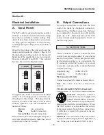
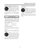
Страница 29: ...15VAC 230VAC B Output Connections All output connections to and from the 9629 control are made by Amphenol connectors There are threeAmphenol connectors the lower one is marked S1 the center one is S2...

Страница 30: ...treated as a stop signal REMOTE EMERGENCY STOP INPUT Pins C D Function When this circuit is opened the 9629 control will initi ate an emergency stop sequence Electrical You can connect a dry relay con...

Страница 31: ...ing Amphenol plug 3106A 22 19P Cord Grip 97 3057 1012 1 Pin Connection Details Connections should be made as shown below Note Pins E F G H J K L M N and P are reserved MOTOR OUTPUT CONNECTION Pins A B...

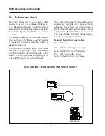
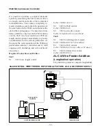
Страница 32: ...pply This is necessary if the 9629 control is fitted with the pulse option and it is desired to synchronize the pulsing of the wire with the pulsing of the weld current Note The Miller range of TIG we...

Страница 33: ...upply to the S2 connector on the 9629 control This signal can be used to provide wire pulsing which is synchronized with the current pulsing The arc length control is connected to the S1 connector on...

Страница 34: ...trol 9629 wire feed control and 9690 arc length control operate automatically to provide coordinated start of the various parameters At the end of the weld operation of the 9640 stop push button initi...

Страница 35: ...control 9629 wire feed control and 9690 arc length control operate automatically to provide coordinated start of the various parameters At the end of the weld operation of the 9627 stop push button i...

Страница 36: ...arried out on a regular basis to verify the correct calibration of the wire feeder and to carry out any small touch up corrections which may be desired from time to time Prior to carrying out this typ...

Страница 37: ...set the low input num ber to the new number calculated in the routine above Switch the control off and on and then repeat the test Check the resulting wire feed speed to verify that it is now accurate...

Страница 38: ...e digit an exact match between the ACTUAL and DISPLAY value may be impossible because of resolution limitations In this case the closest Low Input value should be selected After making all the necessa...

Страница 39: ...s shown are the quantities used to make the main assembly Two columns are included in the list to show the spare parts which it is recommended should be stocked by the user The two levels can be defin...

Страница 40: ...y 1 6 9600 CAB S3 Cable Assembly 1 7 C 1318 006 BL Power Cord 1 8 AS 25 5 Power Supply 1 9 81F4550 RFI Filter 1 10 9600 110 Sub Panel 1 11 240D10 Solid State Relay 1 1 12 9600 11 Isolation Board 1 1 1...

Страница 41: ...9629 Microprocessor Controller 41 Figure 1 Enclosure SUB PANEL GROUND MAIN GROUND...

Страница 42: ...6 AYW400 Switch Operator 1 7 TWC01 Contact Normally Closed 1 1 8 9600 LCD Display 1 1 9 AML21EBA2AA Push button Switch Momentary 2 1 1 10 AML51 E10R Red Cap Extended 1 11 AML51 F10G Green Cap Small 1...

Страница 43: ...9629 Microprocessor Controller 43 Figure 2 Enclosure Door...

Страница 44: ...gnals to and from all the vari ous devices on the board U3 Digital to Analog Converter DAC Receives digital information from the microcon troller and converts it to an analog value to control the moto...

Страница 45: ...9629 Microprocessor Controller 45 Figure 3 9600 10 Board J6 To Start Stop Switches NVRAM Includes Lithium Battery...

Страница 46: ...ied If the circuit is broken the system will disable move ment COMPONENTS SW1 Remote Emergency Stop Selector Switch In the up position towards CR7 the remote emergency stop function is overridden In t...

Страница 47: ...rd J3 To 9600 10 Digital J4 To Cable 9600 CAB S3 J6 To Cable 9600 CAB S2 J5 To Cable 9600 CAB S1 TP3 TP4 TP6 TP5 TP10 TP11 TP8 TP7 TP1 TP2 To Motor Drive J7 To Solid State Relay J8 To Emergency Stop S...

Страница 48: ...to their reduction to a single page size Full size prints of any of these drawings are available free of charge on application to our Electrical Engineering Department Electrical Diagrams The diagram...

Страница 49: ...9629 Microprocessor Controller 49 S1 CONNECTOR...

Страница 50: ...9629 Microprocessor Controller 50 S2 CONNECTOR...

Страница 51: ...9629 Microprocessor Controller 51 S3 CONNECTOR...

Страница 52: ...9629 Microprocessor Controller 52...

Страница 53: ...9629 Microprocessor Controller 53 Interconnection Diagram...

Страница 54: ...99 9 99 9 9 9 99 9 1 0 1 0 0 3 2 0 W I R E S P E E D 7 These two lines display when the control is first switched on and stay on for about 3 seconds the screen then automatically advances to the next...

Страница 55: ...ption has been included in the control F W D J G S P E X X X 8 10 100 50 O E D R E V J G S P E X X X 9 10 100 50 O E D R A P I D S P E E D X X X 10 10 100 75 O n O f f P U L S D W I R 12 R E T R A T S...

Страница 56: ...0 9 9 1 0 19 S S G X N A e Y c s e u a l 20 D I S P Y A Actual e t r c P A t L X X X X i p m X I G H L I T M I 21 0 0 9999 9 Depends on the model H H I G U U T X X P 0 4095 4095 22 H O X X T T A C I...

Страница 57: ...Displays when a jog touch pad is depressed while the system is in a programming screen Displays whenever the emergency stop button is depressed and remains on until it is reset Displays during wire fe...

Страница 58: ...se 22 Low Speed 21 M Maintained Forward 18 Maintained Jog 14 Maintained Reverse 18 Maintenance 36 Mechanical Installation 28 Microcontroller Board 9600 10 44 O Operating Mode 54 Operational Sequence 2...

Отзывы: