9629 Microprocessor Controller
- 15 -
Section VI.
Modes of Operation
A. Operator Mode
This is the mode which is used by the operator to
run the wire feeder. The system is automatically
set to this mode when the control is switched
on.
To set the conditions for operation, the operator
can scroll through the various screens and make
the appropriate changes. These changes will be
displayed on the top line of the display.
As the system is operating, various informa-
tion messages appear on the lower line of the
display.
Display Screens - Upper Line
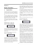
Screen 1 WELCOME SCREEN
This screen appears automatically when the unit
is switched on and remains on the screen for ap-
proximately 3 seconds. It identifies the model
of the control.
The next screen will appear automatically.
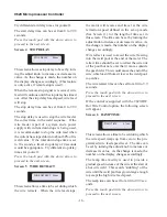
Screen 2 WIRE SPEED
When the second screen appears, it displays the
current level of wire feed speed. If this speed
is correct, the start button can be pressed to im-
mediately initiate wire feed. If the 9629 is part
of a system, a remote signal can initiate the start
delay prior to the wire feeding.
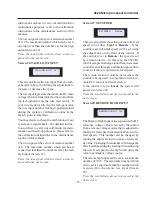
Jetline Engineering
Model 9629
WIRE SPEED
40.0ipm
Speed will be displayed in IPM (inches per min-
ute) or CPM (centimeters per minute). Selection
of IPM or CPM is made in the calibration mode
(see Screen 30)
.
If it is desired to change the speed, this is done
by turning the adjust knob to increase or de-
crease the speed as necessary. As the change
is made, the number on the display changes
accordingly.
The wire feed speed can be adjusted from the
minimum to maximum value which has been
set in the calibration mode (see Screens 21 and
24).
Press the touch pad with the down arrow to
proceed to the next screen.
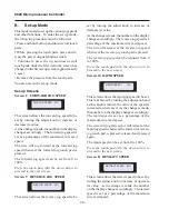
Screen 3 START DELAY
This screen allows a start delay to be set by
turning the adjust knob to increase or decrease
its value. As the change is made, the number on
the display changes accordingly. (This feature is
active only if remote start is used).
When the remote start signal is received, wire
feed will be inhibited until the start delay has
timed out. After the start delay has elapsed,
wire feed will commence at the speed which
has been preset.
The start delay is used to start wire feeding at the
correct time in the weld start up sequence. If the
9629 controlled wire feeder is part of a system
and a power supply with current upslope is be-
ing used, it is recommended to initiate wire feed
when the current has sloped up to about 75% of
its weld value. This will ensure that the weld
pool is correctly established before wire starts to
feed. If, for example, the total time for initial
current and upslope is set to two seconds on the
welding power supply, a wire start delay of ap-
proximately 1.5 seconds would be appropriate.
START DELAY
2.8sec
Содержание 9600 Series
Страница 2: ...9629 Microprocessor Controller 2...
Страница 6: ...9629 Microprocessor Controller 6...
Страница 41: ...9629 Microprocessor Controller 41 Figure 1 Enclosure SUB PANEL GROUND MAIN GROUND...
Страница 43: ...9629 Microprocessor Controller 43 Figure 2 Enclosure Door...
Страница 49: ...9629 Microprocessor Controller 49 S1 CONNECTOR...
Страница 50: ...9629 Microprocessor Controller 50 S2 CONNECTOR...
Страница 51: ...9629 Microprocessor Controller 51 S3 CONNECTOR...
Страница 52: ...9629 Microprocessor Controller 52...
Страница 53: ...9629 Microprocessor Controller 53 Interconnection Diagram...


