computer radio control system
EN
(spring-loaded switch). After you create all of your desired functions,
press the
„F5(Next)“
button to confirm.
7.
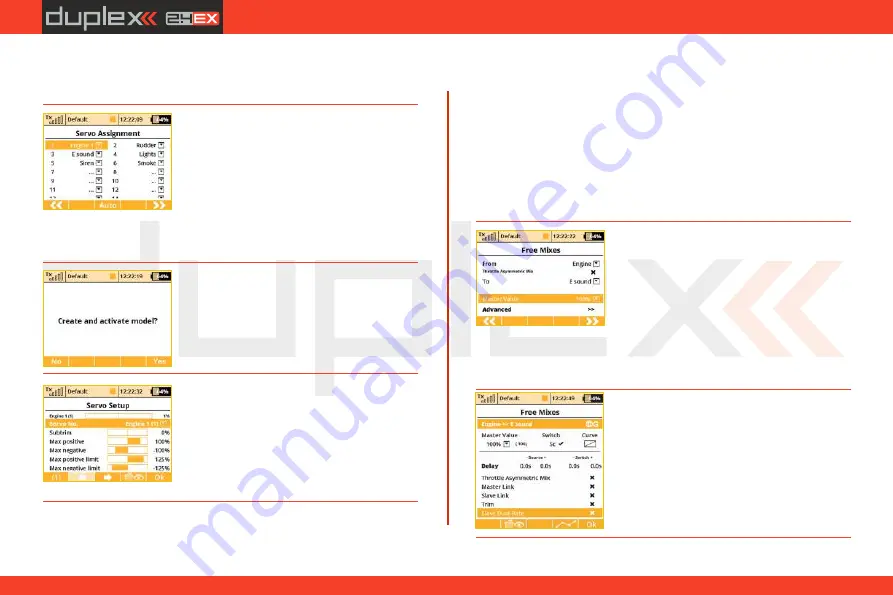
The
"
Servo assignment
“
menu displays
the receiver channels and their transmitter
output assignments. The channels are
assigned in the order that you created the
functions in the previous menu. If you want
to change any of the output assignments,
select the channel you want to edit and
reassign its output. Otherways press
"F5(Next)“
to confirm.
8.
The screen will display a question which
asks if you really want to create and activate
the new model. Press the
„F5(Yes)“
button
to confirm.
9.
The
"
Servo Setup
“
menu is where you
can set all of your servo neutral positions,
servo output throw limits, servo reversing,
delay etc. You should return to this menu
after you have bound your receiver and
transmitter.
See the chapter 8.3: Receiver-
>Binding.
a.
Use the
„F2(Add)“
button to create a
new mixer. Select
„Engine“
in the
„From“
item. Then select „Sound M“ (the name of
the sound function) in the „To“ item. The
item
„Master Value“
represents the
amount of mixing from the input function
Once your transmitter has been bound with a receiver and has been
connected to its power supply, the last step consists of tuning the
servo output functions,
see chapter 8.3.5: Setup of receiver
outputs.
To complete this model we just need to configure a free mixer from
the throttle function to the motor sound module. In this example we
will set a switch to enable/disable the mixer so that when the switch
is
"on“
, the motor sound module is controlled with the throttle
(motor speed). Go to the
"Fine tuning->Free mixers“
menu.
b.
To assign a switch for the activation and
deactivation of the free mixer, press the
"F4(Edit)“
button. Select and edit the
"
Switch
“
item to assign a switch/stick to
enable/disable the mixer.
to the output function for this mixer. With the
„F5(Next)“
button you
will create the mixer and the display will change to show the
overview of your programmed free mixers.
53
Содержание DC-14 II
Страница 1: ...computer radio control system EN CZECH REPUBLIC EN FW 5 xx Part I User Manual DC DS 14 II 2 4GHz...
Страница 2: ...computer radio control system EN 2...
Страница 40: ...computer radio control system EN 40...
Страница 68: ...computer radio control system EN 68...
Страница 69: ...computer radio control system EN 69...
Страница 70: ...computer radio control system EN 70...
Страница 71: ...computer radio control system EN 71...
Страница 72: ...computer radio control system EN JETI model s r o Lomen 1530 742 58 P bor Czech republic EU www jetimodel com...


