16
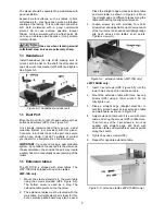
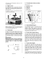
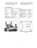
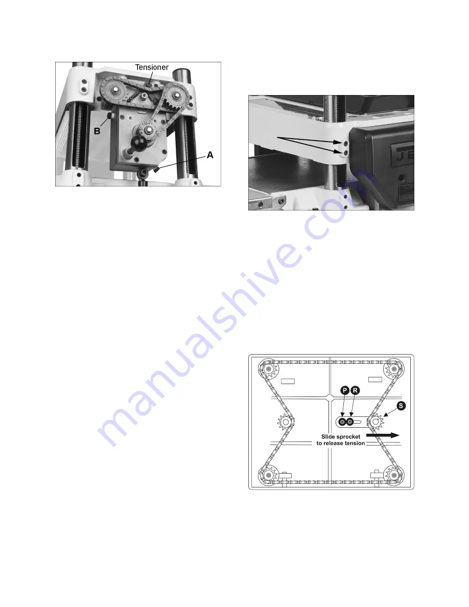
4. Reinstall drain plug (A) and fill gearbox with
clean lubricant through hole (B).
5. Install and tighten filler cap (B).
Figure 9-1
9.2
Belt replacement
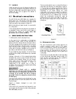
To replace the belt, remove cabinet panel and belt
guard (see Figure 7-1). Rotate the pulleys using the
belt, while gradually walking the belt off one pulley
until it comes free. Use the reverse process to install
the new belt, making sure it is seated completely
onto the pulley grooves. Check for proper tension
(see sect. 7.1).
9.3
Work table parallel to cutterhead
The work table is set parallel to the cutterhead by
the manufacturer and no further adjustment should
be necessary. If your machine is planing a taper,
first check to see if knives or knife inserts are
set properly in the cutterhead
. Then check to see
if main table is set parallel to cutterhead, using the
following method. You will need feeler gauges, and
a dial gauge or home-made gauge block made of
hardwood. This gauge block can be made by
following the dimensions shown in Figure 8-5.
1. Disconnect machine from power source.
2. Place gauge block on main table directly under
a knife edge. Make slight contact by gently
lowering head.
3. Move gauge block to opposite end of table.
Distance from table to knife edge should be the
same at both ends.
4. If the gap difference is greater than 0.004” and
less than 0.016”, perform the adjustment
procedure in
sect. 9.3.1.
If the gap is greater
than 0.016”, use procedure in
sect. 9.3.2
.
9.3.1
Fine adjustment
For gap difference 0.004 to 0.016 inches.
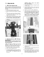
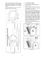
1. On the side of the table that needs correcting,
locate the two socket head cap screws for each
column (Figure 9-2). Loosen both screws for
each column on the side you wish to adjust.
2. Push down or pull up the head assembly in the
desired direction. Hold the assembly in position
and retighten the cap screws.
3. Check table-to-cutterhead parallelism again as
described in the previous section, then repeat
steps 1 through 3 if needed until deviation is
less than 0.004”.
Figure 9-2
9.3.2
Major adjustment
For gap difference > 0.016 inches.
1. Remove cabinet panels.
2. Pivot outfeed table out of the way (or remove it
if cast iron version).
3. Lower head until there is enough motor
clearance to reach under and adjust the
sprockets.
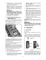
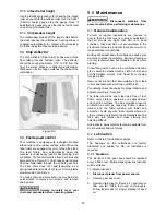
4. Remove bolt (P, Figure 9-3) and loosen bolt (R)
which will allow enough movement of idler
sprocket assembly (S) to release tension on
chain.
Figure 9-3
5. Remove chain from the particular sprocket on
the corner of the base that you need to adjust.
6. Turn the sprocket by hand to bring that corner
into adjustment with the other three corners.
NOTE: Turning sprocket clockwise will increase
the distance between the working table and the
Содержание JWP-15B
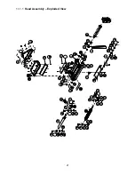
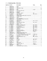
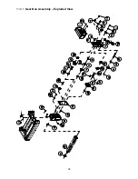
Страница 21: ...21 11 1 1 Head Assembly Exploded View ...
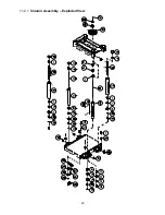
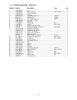
Страница 23: ...23 11 2 1 Column Assembly Exploded View ...
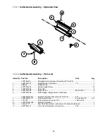
Страница 26: ...26 11 4 1 Gear Box Assembly Exploded View ...
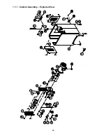
Страница 28: ...28 11 5 1 Cabinet Assembly Exploded View ...
Страница 32: ...32 12 0 Electrical Connections for JWP 15B 15BHH ...
Страница 34: ...34 This page intentionally left blank ...
Страница 35: ...35 This page intentionally left blank ...
Страница 36: ...36 427 New Sanford Road LaVergne Tennessee 37086 Phone 800 274 6848 www jettools com ...

