12
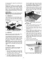
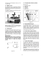
11. Tighten all gib screws on the other two knives
in the same fashion, until all gib screws on the
cutterhead are firmly tightened.
(NOTE: The purpose of this incremental
tightening process is to prevent any slight
deflection or warpage of the cutterhead, and to
ensure that each knife is completely seated into
the slot.)
After installing knives,
check again carefully. Make certain all gib
screws are tightened securely. Loose knives
can be propelled at high speed from a
rotating cutterhead, causing injury.
12. Re-install top cover and dust hood.
7.3
Replacing/rotating knife inserts
(JWP-15BHH only)
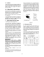
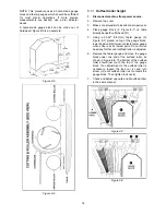
The knife inserts on the JWP-15BHH are four-sided.
When dull, simply remove each insert, rotate it 90°
for a fresh edge, and re-install it.
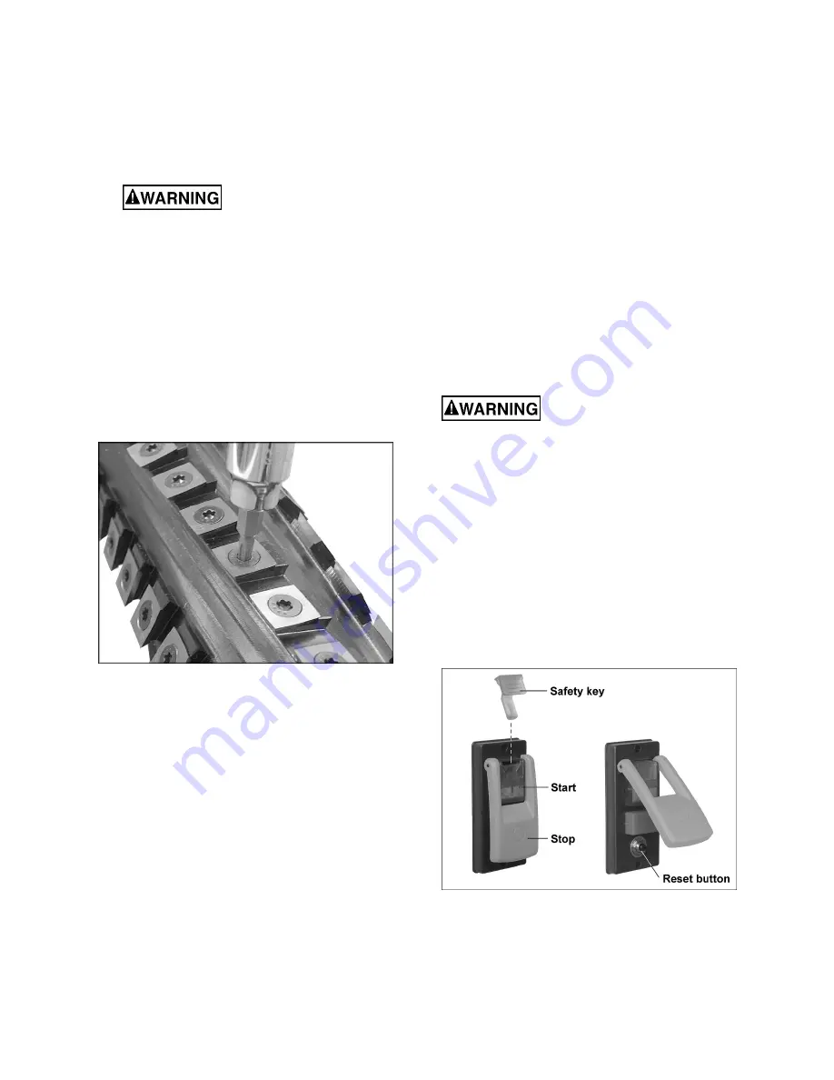
Use a provided star-point driver (F, Figure 5-1) to
remove the knife insert screw.
Figure 7-4
It is advisable to rotate all inserts at the same time
to maintain consistent cutting. However, if one or
more knife inserts develops a nick, rotate only those
inserts that are affected.
Each knife insert has an etched reference mark so
you can keep track of the rotations.
IMPORTANT:
When removing or rotating inserts,
clean saw dust from the screw, the insert, and the
cutterhead platform. Dust accumulation between
these elements can prevent the insert from seating
properly, and may affect the quality of the cut.
To install new knife inserts:
1. Disconnect machine from power source.
2. Remove dust hood and top cover.
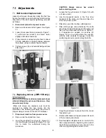
3. Insert provided Torx driver into hole through belt
guard (see B, Figure 7-2). Use this to rotate the
cutterhead during the procedure.
CAUTION:
Always remove hex wrench
before starting planer.
4. Before installing each screw, lightly coat the
screw threads with machine oil and wipe off any
excess.
5. Position knife insert and move it back and forth
to verify there are no burrs or dirt.
6. Hold insert away from the back of the seat (pull
slightly toward yourself if facing the cutting
edge) and allow the screw to pull insert into
position. Note: A slight offset between screw
hole and hole in knife insert is normal. Do not
position insert directly over screw hole, as it
could ride up on the back of the seat and
potentially cause cracking of the tip.
7. Securely tighten each knife insert screw before
operating the planer.
IMPORTANT:
Maximum torque for tightening the
screws is 45 to 55 inch pounds (3.75 to 4.6 foot
pounds).
Make sure all knife insert
screws are tightened securely. Loose inserts
can be propelled at high speed from a rotating
cutterhead, causing injury.
8.0
Operation
8.1
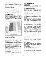
Start switch
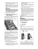
See Figure 8-1.
Press green switch to start planer. Press red switch
to stop.
To prevent unauthorized or accidental starting of the
planer, remove safety key from switch and store in
a safe place. Key must be reinserted to start planer.
Figure 8-1
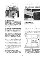
The planer is equipped with overload protection. If
an excess of current is detected, the machine will
shut off to prevent damage to motor. If this occurs,
wait a few minutes for the machine to cool down,
then press the reset button behind the stop paddle.
Содержание JWP-15B
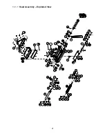
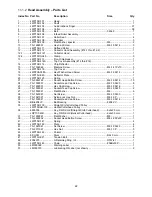
Страница 21: ...21 11 1 1 Head Assembly Exploded View ...
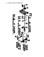
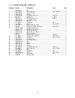
Страница 23: ...23 11 2 1 Column Assembly Exploded View ...
Страница 26: ...26 11 4 1 Gear Box Assembly Exploded View ...
Страница 28: ...28 11 5 1 Cabinet Assembly Exploded View ...
Страница 32: ...32 12 0 Electrical Connections for JWP 15B 15BHH ...
Страница 34: ...34 This page intentionally left blank ...
Страница 35: ...35 This page intentionally left blank ...
Страница 36: ...36 427 New Sanford Road LaVergne Tennessee 37086 Phone 800 274 6848 www jettools com ...


