13
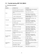
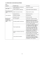
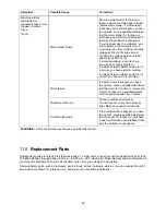
If the planer shuts off frequently, refer to
sect. 10.0
Troubleshooting
.
8.2
Depth of Cut
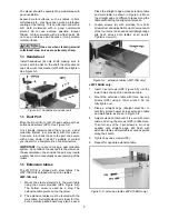
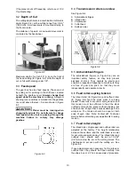
The cutting depth scale is a combination inch/metric
scale (Figure 8-2), with a cutting range from 0 to 6"
(152.4mm). A manual scale is mounted directly to
the front column.
The distance of upward or downward movement is
controlled by the handwheel.
Figure 8-2
Maximum depth of cut is 3/16". A lip on the front of
the head casting (B, Figure 8-2) limits the depth of
cut on full width planing under 1/8".
8.3
Feed speed
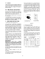
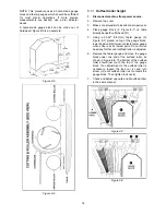
The gear box has two feed speeds. These are set
by pulling out or pushing in the shift lever, located
beneath the gearbox cover.
Always change feed
speed while the machine is running.
A diagram
showing lever positions is molded into the gearbox
cover just above the lever. It is also shown in Figure
8-3.
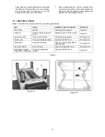
Planer must be running when
changing feed rate. Do not attempt to change
feed speed while stock is passing through the
machine. Failure to comply may damage
gearbox.
Figure 8-3
8.4
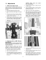
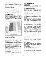
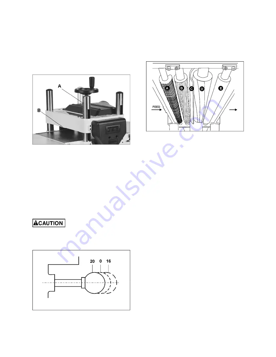
Transmission rollers overview
See Figure 8-4.
A. Anti-kickback fingers
B. Infeed roller
C. Chipbreaker
D. Cutterhead
E. Outfeed roller
Figure 8-4
8.5
Anti-kickback fingers
The anti-kickback fingers (A, Figure 8-4) are an
important safety feature, as they help prevent
kickback of stock. They operate by gravity and
should be inspected frequently to make sure they
are free of gum and pitch, so that they move
independently and operate correctly.
8.6
Feed rollers spring tension
The infeed roller (B, Figure 8-4) and outfeed roller
(E, Figure 8-4) feed the stock while it is being
planed. These rollers are under spring tension and
this tension must be sufficient to feed the stock
uniformly through the planer without slipping, but
should not be so tight that it causes damage to the
workpiece. The tension should be equal at both
ends of each roller. Note: Contact JET Technical
Service before attempting any adjustments to spring
tension.
8.7
Feed rollers height
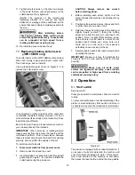
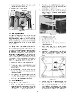
The infeed roller, chipbreaker and outfeed roller are
adjusted at the factory. The height relationship
between these items and the cutterhead is crucial
for accurate and safe planing. The infeed roller and
outfeed roller should each be set at 0.032"
(0.81mm) below the arc of the cutting knives. The
chipbreaker is set even with the cutting arc. See
Figure 8-6.
If any adjustments are necessary for the infeed or
outfeed roller, they should be done carefully. Use
the steps in
sect. 8.7.1
as an example of procedure.
Содержание JWP-15B
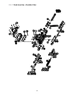
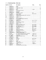
Страница 21: ...21 11 1 1 Head Assembly Exploded View ...
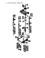
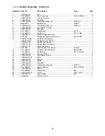
Страница 23: ...23 11 2 1 Column Assembly Exploded View ...
Страница 26: ...26 11 4 1 Gear Box Assembly Exploded View ...
Страница 28: ...28 11 5 1 Cabinet Assembly Exploded View ...
Страница 32: ...32 12 0 Electrical Connections for JWP 15B 15BHH ...
Страница 34: ...34 This page intentionally left blank ...
Страница 35: ...35 This page intentionally left blank ...
Страница 36: ...36 427 New Sanford Road LaVergne Tennessee 37086 Phone 800 274 6848 www jettools com ...


