background image


21

other gouges. Most average sized bowl work can 
be accomplished with a 3/8" or 1/2" bowl gouge.  

A 1/4" bowl gouge is best suited for smaller bowls 
and light finishing cuts. Larger 3/4" and 1" bowl 
gouges are only used for extremely large pieces. 

Large domed scrapers can also be used to help 
clean up the interior surfaces of bowls. A light 
touch with the scraper slightly tilted will eliminate 
some of the ridges occasionally left by an 
inexperienced bowl gouge. 

9.7

  Bowl Turning Techniques 

9.7.1

  To Shape Outside of Bowl 

1.  Odd shaped burls, crotches and other irregular 

shaped blanks require special preparation 
before mounting in a chuck or onto a 
faceplate. Remove the bark, if there is any, 
from what appears to be the center of the top 
of the workpiece. 

2.  Drive spur center into the top of the workpiece 

with a mallet or dead blow hammer. 

3.  Slip the spur center into the headstock taper 

and bring the tailstock with a live or ball 
bearing center into position. Lock the tailstock 
to the bed and advance the tailstock spindle in 
order to seat the cup center into the 
workpiece. Tighten the ram locking handle. 

4.  Turn workpiece by hand to ensure proper 

clearance. 

5.  Start lathe at lowest speed and bring it up to 

the maximum safe speed for the size of work 
to be turned. If the machine starts to vibrate, 
lower the speed until vibration stops. 

6.  Rough out the outside of the bowl with the 1/2" 

deep fluted bowl gouge, holding the handle of 
the tool firmly against your hip. For best 
control, use your whole body to move the 
gouge through the workpiece. 

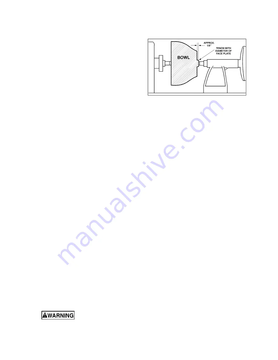
7.  As the bowl takes shape, work on the bottom 

(tailstock end) to accommodate attaching a 
face plate. 

8.  Turn a short tenon (about 1/8" long) the size of 

the hole in the faceplate. See Figure 9-10. This 
will allow centering the workpiece when the 
faceplate is attached. 

(NOTE: If you plan to use a chuck, turn a 
tenon of the appropriate length and diameter 
to fit your chuck.) 

9.  Stop the lathe, remove workpiece and attach 

face plate or chuck (

see section 9.6.1 

"Mounting Stock"

). 


The surfaces of faceplate 

and workpiece should mount flush to each 
other.


10.  Finish turning the outside of bowl with 1/2" or 

3/8" bowl gouge. Leave additional material at 
base of bowl for support while turning interior. 
This will be removed later. 


Figure 9-10 

9.7.2

  To Shape Interior of Bowl 

1.  Stop lathe and move tailstock away. (You may 

want to remove the center from the tailstock to 
avoid bumping it with your elbow.) 

2.  Adjust tool support in front of the bowl just 

below centerline, at a right angle to the lathe 
ways. 

3.  Rotate workpiece by hand to check clearance. 

4.  Face off top of bowl by making a light shearing 

cut across the top of workpiece, from rim to 
center. 

5.  Place 1/2" bowl gouge on tool support at 

center of the workpiece with the flute facing 
top of bowl. The tool handle should be level 
and pointed toward the four o'clock position, as 
shown in Figure 9-11. 

6.  Use the left hand to control cutting edge of 

gouge, while right hand swings tool handle 
toward your body (Figure 9-11). The flute 
should start out facing top of workpiece, and 
rotate upward as it moves deeper into the bowl 
to maintain a clean even curve. As the tool 
goes deeper into the bowl, progressively work 
out toward the rim. It may be necessary to turn 
the tool support into the piece as you get 
deeper into the bowl. 

(NOTE: Try to make one, very light continuous 
movement from the rim to the bottom of the 
bowl to ensure a clean, sweeping curve 
through the piece.  

Should there be a few small ridges left, a light 
cut with a large domed scraper can even out 
the surface.) 

Содержание JWL-1840DVR

Страница 1: ...x 40 Woodturning Lathe Models JWL 1840EVS JWL 1840DVR JET 427 New Sanford Road LaVergne Tennessee 37086 Part No M 719600 Ph 800 274 6848 Edition 3 01 2017 www jettools com Copyright 2017 JET JWL 1840...

Страница 2: ...upply 15 Give your work undivided attention Looking around carrying on a conversation and horse play are careless acts that can result in serious injury 16 Keep visitors a safe distance from the work...

Страница 3: ...ier the cord Familiarize yourself with the following safety notices used in this manual This means that if precautions are not heeded it may result in minor injury and or possible machine damage This...

Страница 4: ...ace plate Installing removing 14 7 14 Checking center alignment 14 7 15 Speed Range Adjustment JWL 1840EVS only 14 8 0 Operating controls 15 8 1 AC Inverter JWL 1840EVS only 15 8 2 DVR JWL 1840DVR onl...

Страница 5: ...irements single phase 230V single phase 230V Starting amps 3 A 0 82 A Running amps no load 2 A 0 48 A Power transfer V belt V belt Drive electronic variable speed inverter control digital variable rel...

Страница 6: ...rest post diameter 1 in 25 4 mm 1 in 25 4 mm Leg footprint 54 x 20 in 1372 x 508 mm 54 x 20 in 1372 x 508 mm Bed length 53 in 1346 mm 53 in 1346 mm Bed width 7 1 8 in 181 mm 7 1 8 in 181 mm Bed gap 1...

Страница 7: ...running satisfactorily 2 Inspect contents for shipping damage if any is found report it to your distributor 3 Compare contents of shipping carton with the contents list in this manual Report shortage...

Страница 8: ...t leg casting 7 Install headstock tool support and tailstock and both studs O Figure 5 6 5 5 Tool shelf The tool shelf N can be mounted to either end of lathe with screws and washers HP004 5 5 6 Guard...

Страница 9: ...purchased separately See our website for information The spindle comparator consists of two centers inserted into the brackets at rear of lathe The comparator is used to mount a finished or reference...

Страница 10: ...grounding plug The plug must be inserted into an appropriate outlet that is properly installed and grounded in accordance with all local codes and ordinances Improper connection of the equipment groun...

Страница 11: ...lockwise until it engages the threads Always engage locking handle A before operating lathe 7 2 Tailstock movement To slide tailstock push locking handle C Figure 7 3 down toward bed Push handle up to...

Страница 12: ...when turning off the bed using the headstock at an angle Make sure the clamp bushings K are pulled apart sufficiently to accept tool rest post Figure 7 6 7 7 Locking handles Locking handles such as H...

Страница 13: ...st the insertion by attempting to pull the center out of the quill by hand It should remain secure within the quill 3 Always tighten quill locking handle M once the live center has been properly posit...

Страница 14: ...ure 7 12 center alignment 3 View the center points from top and side to make sure they align 4 If centers do not align unlock headstock and pivot it slightly There should be enough play in headstock t...

Страница 15: ...tch to continue When turning with a face plate make sure both set screws on face plate are tight before reversing spindle direction Failure to comply may cause face plate to spin loose from spindle 8...

Страница 16: ...remove any rust spots and apply paste wax to prevent buildup of rust and finishes 5 Tool rest use a mill file to remove nicks and dings 6 Spindle tapers should be clean and free of dust and chips for...

Страница 17: ...e of checks cracks knots and other defects It should be cut 1 8 to 1 4 larger than the finished diameter and may require additional length so the ends can be removed later Larger stock should have the...

Страница 18: ...er clearance 12 Start lathe at lowest speed and bring it up to the appropriate RPM for the size of workpiece used Consult digital readout on the headstock Figure 9 5 9 5 Cutting Techniques 9 5 1 Rough...

Страница 19: ...ed depth as shown in Figure 9 8 Figure 9 8 5 Repeat from the left side The two cuts should meet at the bottom and leave a clean V cut 6 Additional cuts may be taken to add to either the depth or width...

Страница 20: ...is not a requirement but is handy when working on more than one piece at a time Rather than removing screws you simply open the chuck and change workpieces The most popular ones are four jaw scroll c...

Страница 21: ...8 long the size of the hole in the faceplate See Figure 9 10 This will allow centering the workpiece when the faceplate is attached NOTE If you plan to use a chuck turn a tenon of the appropriate leng...

Страница 22: ...nding and cause heat check in some woods 2 Begin with fine sandpaper 120 grit and progress through each grit using only light pressure Coarser sandpaper tends to leave deep scratches that are hard to...

Страница 23: ...lock loosen two set screws on spindle pulley E Figure 9 12 with 3mm hex key and slide spindle pulley into proper position Retighten set screws and disengage spindle lock When pulleys and belt are pro...

Страница 24: ...oo low Reposition tool rest height Tool rest set too far from workpiece Reposition tool rest closer to workpiece Improper tool being used Use correct tool for operation Headstock moves when applying p...

Страница 25: ...lso display when power is turned off Er14 PFC Fault Problem with power factor correction unit Repair is advised by qualified personnel Er50 Overheat Heatsink temperature exceeds allowable threshold Er...

Страница 26: ...650 900 10 to 12 255 540 750 12 to 14 220 460 640 14 to 16 190 400 560 16 to 20 175 325 450 20 to 24 175 260 375 13 0 Optional accessories These accessory items purchased separately can enhance the fu...

Страница 27: ...5 00 p m CST Having the Model Number and Serial Number of your machine available when you call will allow us to serve you quickly and accurately Non proprietary parts such as fasteners can be found at...

Страница 28: ...WL1640EVS 127 Spindle Lock Pin 1 28 JWL1442 121 Bracket 1 29 4224B 143 Wear Resistant Washer 1 30 4224B 1122E Sliding Plate 1 31 TS 0253031 Socket Head Button Screw 10 24x1 2 6 32 JWL1640EVS PPA Pivot...

Страница 29: ...73 TS 0060061 Hex Bolt 3 8 16x1 1 4 2 74 JWL1442 164 Knock Out Rod 1 76 JWL1442 108 Wave Washer 1 77 JWL1642 196E Strain Relief PG 13 5 1 78 JWL1640EVS 178 Plate 1 79 TS 0206041 Socket Head Cap Screw...

Страница 30: ...30 14 2 1 JWL 1840DVR Headstock Assembly Exploded View...

Страница 31: ...1 30 4224B 1122E Sliding Plate 1 31 TS 0253031 Socket Head Button Screw 10 24x1 2 6 32 JWL1640EVS PPA Pivot Pin Assembly includes 33 thru 38 1 33 JWL1442 176 Index Bushing 1 34 JWL1640EVS 134 Pivot In...

Страница 32: ...270 Rubber Grip 1 82 JWL1640EVS 182 Rubber Grip 1 83 JWL1840DVR 183 Mounting Plate 1 84 TS 0253031 Socket Head Button Screw 10 24x1 2 3 86 TS 0733031 Ext Tooth Lock Washer 10 1 87 TS 0271111 Set Scre...

Страница 33: ...x1 2 4 9 JWL1640EVS 160 Pan Head Screw 10 24x1 1 10 JWL1640EVS CA Controller Assembly includes 11 thru 23 1 11 JWL1642 143 Variable Speed Knob 1 12 LM000066 Control Panel Label 1 13 JWL1640EVS 213 Mai...

Страница 34: ...34 14 4 1 JWL 1840DVR Controller Assembly Exploded View...

Страница 35: ...Cover 1 29 TS 1533042 Machine Screw M5 x 12 4 30 JWL1840DVR 230 Clamp PG 21 2 31 JWL1840DVR 231 Tube 1 32 JWL1840DVR 232 Ferrite Core 1 33 JWL1840DVR 233 Connection Cord Control Panel to HMI 1 34 4224...

Страница 36: ...36 14 5 1 JWL 1840EVS DVR Bed and Stand Assembly Exploded View...

Страница 37: ...ead Button Screw 10 32x5 8 1 24 JWL1015 137 Tailstock Lock Handle 1 25 JWL1840EVS 325 Tailstock Casting 1 26 JWL1440 226 Handwheel 1 27 JWL1442 211 Handle 1 28 TS 0267041 Set Screw 1 4 20x 3 8 2 29 JW...

Страница 38: ...bly OPTIONAL Parts List Index No Part No Description Size Qty 719401 20 Extension Bed w Post includes 1 thru 6 1 1 JWL1440 301 Extension Bed 20 1 2 TS 0209071 Socket Head Cap Screw 3 8 16x1 1 2 4 3 TS...

Страница 39: ...Screw 5 16 18 x 1 4 2 14 8 1 JWL 1840EVS DVR Comparator Kit OPTIONAL Exploded View 14 8 2 JWL 1840EVS DVR Comparator Kit OPTIONAL Parts List Index No Part No Description Size Qty 719601 Spindle Compar...

Страница 40: ...3 4 3 3 3 2 3 1 3 0 29 28 27 2 6 2 5 2 4 2 3 2 2 2 1 20 19 18 1 7 1 6 1 5 14 13 12 11 10 9 8 7 6 5 4 3 2 BRAKE RESISTOR purple Orange Red Brown Gray Red Orange Black Brown Yellow Blue Gray Purple Gre...

Страница 41: ...41 15 2 Schematic for JWL 1840DVR only...

Страница 42: ...42...

Страница 43: ...eeded JET has Authorized Service Centers located throughout the United States For the name of an Authorized Service Center in your area call 1 800 274 6846 or use the Service Center Locator on the JET...

Страница 44: ...44 427 New Sanford Road LaVergne Tennessee 37086 Phone 800 274 6848 www jettools com...

Отзывы: