background image

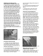
ATTACHING THE EXTENSION WING

1. Attach the large hex nuts with cap screws 
(item #13 from the parts list on page 2) to the 
extension wing.

2. Loosen the large hex nuts to allow enough 
space for them to slide into the groove that 
runs along the side of the table slide (Fig. 26).

3. Slide the extension wing along the groove 
and position it at your desired location. 
Tighten the cap screws so that the extension 
wing is securely fastened to the table slide. 
You can adjust the position of the extension 
wing to locate anywhere along the side of the 
table slide depending on the cutting operation 
being performed. Locate the extension wing in 
the optimal position wherever additional 
support of the workpiece is needed.

Additional extension wings are sold separately 
if you wish to add another to your system. Ask 
your JessEm dealer for item #07511.

FIG. 26

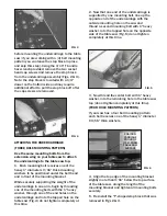
LEVELING THE EXTENSION WING

1. There are two set screws located above 
and below the mounting holes for the 
extension wing (Fig. 27). If the extension wing 
is not level with the table slide you can adjust 
for level by first loosening the mounting 
screws slightly. Then tighten the upper set 
screw to lower the outside edge. Or, tighten 
the lower set screw to raise the outside edge. 
Re-tighten the socket head cap screws after 
making adjustments for level.

FIG. 27

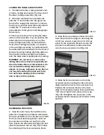
ATTACHING THE POWER SWITCH

1. If your saws power switch was attached to 
the left extension wing you may be able to 
attach it in a similar manner under the front 
edge of the saws table top. Or you may use 
the bracket (item #5 from the parts list on 
page 2) and mounting screws provided to 
attach the power switch to the bottom of the 
undercarriage for the Mast-R-Slide. There are 
two tapped holes adjacent to the shot pin 
locking knob under the front edge of the 
undercarriage to mount the bracket on 
(Fig.28). Use the hardware from your switch 
to attach the switch box to the bracket.

FIG. 28

ATTACH THE FLIP STOP

1. The flip stop slides in the “T”-track that 
runs along the top front of the miter fence 
and fence extension. With the pointer lined 
up with the “STOP POSITION” mark on the 
scale you can read measured cuts on the 
fence extension rod (Fig. 25).

FIG. 25

Содержание Mast-R-Slide 7500

Страница 1: ...is sold at time of purchase We reserve the right to make positive changes to our products at our discretion without notification 61 Forest Plain Road Orillia Ontario Canada L3V 6H1 Toll Free 1 866 27...

Страница 2: ...rds when operating any power tool or machinery Always use proper guards and safety devices when operating power tools and machinery Carefully check accessories or other equipment before each use Do no...

Страница 3: ...hat can be accessed from underneath the extension wing 2 Once your extension wing is removed the front and rear rails for guiding the saw s rip fence need to be repositioned to the right or cut off wh...

Страница 4: ...completely at this time FOUR HOLE MOUNTING PATTERN If your saw has a four bolt mounting pattern each bolt receives one of the heavy 1 diameter X 3 16 thick washers FIG 5 FIG 3 ATTACHING THE UNDERCARRI...

Страница 5: ...e the stop bumper from Fig 1 FIG 7 FIG 8 FRONT FENCE MOUNTING T NUT FRONT FENCE MOUNTING T NUT ADJUSTING THE TABLE SLIDE 1 The lower carriage assembly has a series of button head cap screws A and set...

Страница 6: ...ration If after all adjustments have been made and you are not happy with the cut quality you may investigate this alignment in greater detail later on if necessary 2 Adjust the two outer set screws i...

Страница 7: ...Do not overload the sliding table with heavy objects or a heavy workpiece at any time as you may risk causing the table saw to tip over and cause damage to the machine and or injury to the operator AS...

Страница 8: ...has one tapped hole and two through holes and is designed to slide with the fence in the mitering position Fig 19 Two of the tapped holes contain set screws for locking the T nut in a fixed position T...

Страница 9: ...AW A B C FIG 23 OPERATION OF THE MITER FENCE 1 There are four knobs used to make adjustments to the fence position Fig 23 The two brass fence adjustment knobs are used to adjust the fence from side to...

Страница 10: ...the extension wing is not level with the table slide you can adjust for level by first loosening the mounting screws slightly Then tighten the upper set screw to lower the outside edge Or tighten the...

Страница 11: ...blade to 90 degrees and also line the fence face up with the zero on the angle scale Then tighten the set screw as shown in Fig 30 Recheck the three positions for squareness and repeat steps 1 thru 5...

Страница 12: ...t R Lift Excel II Rout R Lift II Mast R Lift II Other Products From JESSEM TOOL COMPANY www jessem com Clear Cut Stock Guides Model 02202 Model 02120 Model 02310 Model 04215 Tools That Make A Differen...

Отзывы: