Chlorinator C 2700
BW 2 03 01 / 1
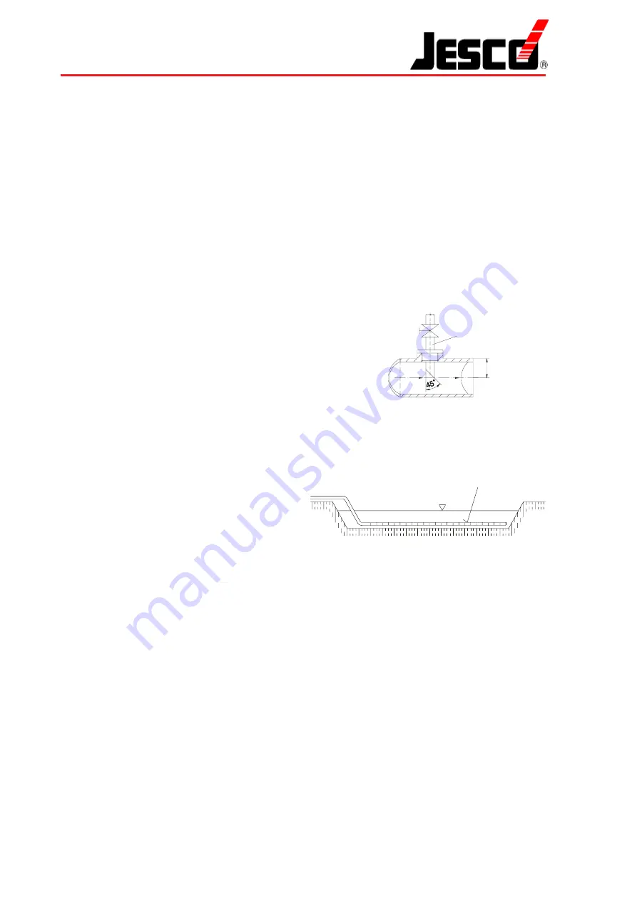
Injection Nozzle
The chlorine injection fittings or chlorine solution injectors
are made from PVC and are fitted with a shutoff valve
(ball cock) and injection piping, which, for installation, is
shortened to half of its diameter with a 45° diagonal cut.
The injection nozzles are integrated either in water-
bearing lines or in open basins at such points where
turbulences enable a good mixture.
For injection into open basins, drains or induction
manifolds, long, perforated pipes closed at the end are
suitable, which are tied to the bottom under water. Thus
a fine and large-area distribution can be ensured.
Safety Blowoff Line
The PE tubing, which is part of the packing unit, is
connected to the center chamber of the chlorinator and
either laid outside with inclination or led to the sensor of
the gas warning device (25), depending on the local
conditions. The tubing is used to carry off chlorine gas,
if the safety valve installed in the center chamber of the
chlorinator has responded.
Gas Supply
Direct Gas Delivery
Chlorine is available in steel cylinders of 65 kg and steel
barrels of 500 and 1,000 kg. Because of the large
quantities required, we recommend to use always barrels,
as only 1 % of the contents may be delivered hourly as
gas at a temperature of 20° C. For chlorine deliveries of
up to 25 kg/h, at least 3 barrels of 1,000 kg should be
connected for direct gas supply.
Operating and Maintenance Instructions
Packing
The C 2700 equipment is packed individually because of
its size and variable accessories. Refer to the delivery
note for the actual scope of delivery.
Notes on Installation
Before installation carefully check the location in which
the chlorinator and tank are to be mounted, according to
the directions of the local authorities. In general, the
standardized safety rules for "Chlorination of Water"
apply.
—
Chlorine tank and chlorinator must be located in
different rooms.
—
The floors of these rooms must not be underground.
— Escaping chlorine gas must not enter other lower
rooms, wells, mines or drains.
— The chlorine rooms must not be connected to other
rooms. A fireproof and gastight separation is required.
Make sure that the doors open outwards and always
without a key from inside.
— Each room is to be provided with small ventilation
openings in the floor and ceiling. These openings
must directly lead outside, and their cross sections
should not exceed 40 cm
2
.
— In the case of unfavourable locations, e.g. near
schoolyards or rest-cure meadows, gas warning
devices with visual and acoustic signaling are to be
installed instead of ventilation openings. They must
be coupled with an automatic sprinkler system.
Delayed activation is admissible.
—
It is important
to use always appropriate tools. Make
sure that
two
fixed spanners are used for detaching
and connecting chlorine lines in order to avoid
unadmissible loading of the device components.
Ejector Water Supply
The numbers mentioned below refer to the schematic
diagram on page 6.
In order to operate a full-vacuum chlorinator, the ejector
(14) must be provided with the appropriate motive water
pressure and the corresponding quantity of motive water.
For the accurate values, see the characteristic curves for
ejectors. If the existing water pressure is not sufficient
according to the ejector data sheet, a booster pump (20)
must be connected. The non-return valve (13) mounted
on the ejector prevents the motive water to return to the
chlorine gas vacuum line if the motive water supply is
switched off or if the ejector is faulty.
As it cannot be excluded that the non-return valve leaks
due to contamination, a motor ball cock (12) must be
opened in dependence on the booster pump (20). Before
entering the ejector, the line must be straight approx.
20 x DN in axial direction of the ejector. A dirt trap with a
mesh aperture of less than 0.5 mm should be used in any
case, no matter if a booster pump is part of the installation
or not.
Chlorine Solution Line
The chlorine solution produced in the ejector is led to the
the injection nozzle (16) via a PVC piping and non-return
valve (15). After the ejector, the line should be straight (5
x DN). In order to avoid pressure losses in the solution
line, use as little bends and fittings as possible.
Chlorine solution from ejector
perforated pipe
e.g. cooling-water basin
Chlorine Evaporation
Liquid chlorine deliveries are recommended for quantities
of more than 25 kg/h. With the help of an evaporator (see
MB 2 05 01), the liquid chlorine is converted into gas by
electrical heating and then led to the chlorinator as
described before.
Shutoff valve
Injection
piping
1/2 DN
Lutz-Jesco GmbH
Improved changes are always reserved without notice.


