7
1.
Connect the 2 black wires (B) together using a UL listed
wire connector.
2.
Connect the 2 white wires (D) and the green (or bare) ground
wire (of the oven cable) using a UL listed wire connector.
3.
Connect the 2 red wires (G) together using a UL listed
wire connector.
4.
Install junction box cover.
Install Oven
1.
Using 2 or more people, lift oven partially into cabinet
cutout. Use the oven opening as an area to grip.
NOTE:
Push against seal area of oven front frame
when pushing oven into cabinet. Do not push against
outside edges.
2.
Push against the seal area of the front frame to push
the oven into the cabinet until the back surface of the
front frame touches the front wall of the cabinet.
3.
Push oven completely into cabinet and center oven into
cabinet cutout.
4.
Remove the tape from the black front trims and remove
the zip tie from the mounting spacer.
■
Securely fasten the oven to the cabinet using the
#8-14 x 1" screws provided.
■
Insert screws through the holes in the black trim
aligning with the holes in the oven frame and mounting
spacers already in place. Do not overtighten screws.
A. Oven frame
B. Mounting spacer
C. Oven frame hole
D. Black trim piece
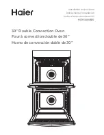
5.
The bottom vent is shipped in the foam packing at the top
of the oven. Install the bottom vent (C) as follows:
■
Align vent tab (B) with oven frame (A) as shown.
■
Using one #8-18 x ³⁄
8
" screw (D) on each side of the vent
tab (B), fasten the vent securely to the oven.
6.
Replace oven racks.
7.
Replace the oven door. See the “Replace Oven
Door(s)” section.
8.
Check that door is free to open and close. If it is not,
repeat the removal and installation procedures. See
“Prepare Built-In Microwave/Oven Combination” section.
9.
Reconnect power.
10.
The display panel will light briefly, and “PF” should appear
in the display.
11.
If the display panel does not light, please reference
the “Warranty” section of the Use and Care Guide.
A. Oven frame
B. Vent tab
C. Bottom vent
D. #8-18 x ³⁄
8
" screws
A
C
D
B
A
C
D
B
B