background image

8

1.  FM INDOOR ANTENNA

Connect the supplied antenna (the
wire lead) to a 300

/75

adapter

and connect the adapter to the 75

T-shaped FM antenna terminal, as
shown in the Rear Panel Connection
Diagram. Change the position of the
antenna until you get the best recep-
tion of your favorite stations.

2.  FM OUTDOOR
ANTENNA

An outdoor FM antenna may be used
to further improve the quality of
reception. Disconnect the indoor
antenna before replacing it with the
outdoor one. A 75

/300

adapter

must be used.

3.  AM LOOP ANTENNA

Tune in your favorite AM station and
position the loop antenna for best
reception. Try other stations and find
the position that gives the best overall
reception. When this unit is mounted
in a rack or placed on a shelf with
insufficient space behind, hang the
antenna on a wall in the direction
which gives the best reception.

NOTE:

If noise is heard during AM

reception, move the antenna for bet-
ter reception. To prevent undesired
noise, the AM LOOP ANTENNA
should be located at least 30 cm
away from the remote control wiring.

4.  SYSTEM GROUND
TERMINAL

To reduce hum to a minimum, con-
nect the ground lead from your
turntable to this terminal.

5.  PHONO INPUT JACKS

Input for TURNTABLE with an MM
cartridge having 47K ohms of load
impedance. Connect shielded cables
from your phono to the LEFT and
RIGHT input jacks.

NOTE:

Do not place your

TURNTABLE on a speaker enclosure.
This will avoid howling caused by
transmission of the speaker vibration
to the TURNTABLE.

6.  TV/AUX INPUT JACKS

This extra stereo input is provided for
any source you want to hear. An
additional compact disc player, a
tape recorder, a video cassette
recorder (VCR) etc., can be plugged
into these jacks.

7.  CD INPUT JACKS

Connect the output cables of a com-
pact disc player to these jacks.

8. TAPE 1 PLAY JACKS

Connect the line output of your 
CASSETTE DECK to these jacks.

9.  TAPE 1 REC JACKS

Connect the line input of your 
CASSETTE DECK to these jacks.

10.  TAPE 2 MONITOR
PLAY JACKS

Connect the line output of your
CASSETTE DECK to these jacks. This
input may be connected to the line
output of the audio processor like an
optional graphic equalizer or a Digital
Signal Processor.

11.  TAPE 2 MONITOR REC
JACKS

Connect the line input of your
CASSETTE DECK to these jacks. EQ
controls, loudness and volume set-
tings have no effect on the signal
from this output for recording. To
monitor this input source while
recording, press the TAPE 2 MONI-
TOR button (MONITOR ON position).
These REC jacks may be used for the
line input of the audio processor like
an optional graphic equalizer or a
Digital Signal Processor.

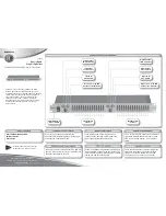
AM LOOP ANTENNA SETTING

Stand and place it on a shelf
or hang it on a wall.

LEG

Rear Panel Connections

 JSR655om (a) qx  7/28/98 9:54 AM  Page 10

Содержание JSR655

Страница 1: ...JSR655 230V Audio andVideo Receiver O W N E R S M A N U A L JSR655om a qx 7 28 98 9 54 AM Page 2...

Страница 2: ...electric shock to persons The exclamation point within an equilateral triangle is intended to alert the user to the presence of important operating and maintenance servicing instructions in the litera...

Страница 3: ...om the AC outlet and disconnect all wires to antennas and other components Do Not Open the Cabinet Do not attempt to service this unit Tampering with internal components can cause fire or shock and ma...

Страница 4: ...eadphones SelRec Sel Bass Treble Balance DOLBY SURROUND P R O L O G I C JSR655 DOLBY SURROUND RECEIVER PRO LOGIC DOLBY SURROUND MHz FM AM MONO SEARCH TAPE MONITOR PRESET MEMORY MS MIN DELAY TIME SLEEP...

Страница 5: ...for balancing the relative sound volume of the left and right channel speakers Clockwise rotation reduces the volume from the left speaker counterclockwise rotation reduces the volume from the right...

Страница 6: ...eption of an FM stereo broad cast The display window shows STEREO MONO The left and right channel signals detected from an FM stereo broadcast are mixed and reproduced through both chan nels If you wa...

Страница 7: ...ct to the AUDIO OUTPUT jacks of a VCR Red and White jacks 22 LOUDNESS BUTTON Press this button to compensate for the response of the human ear at low listening levels known as the Fletcher Munson hear...

Страница 8: ...13 14 20 17 15 21 19 1 2 16 14 PLAY OUT REC IN PLAY OUT IN AUDIO VIDEO OUT OUT IN OUT AUDIO VIDEO OUT L R OUT PLAY VCR 2 IN ANTENNA FRONT CENTER VIDEO MONITORS REAR SPEAKERS REMOTE CONTROL FRONT SPEAK...

Страница 9: ...hielded cables from your phono to the LEFT and RIGHT input jacks NOTE Do not place your TURNTABLE on a speaker enclosure This will avoid howling caused by transmission of the speaker vibration to the...

Страница 10: ...mplifier input to these jacks FRONT MAIN IN When a separate pre amplifier is con nected and this unit is used as a power amplifier connect the pre amplifier output to these jacks NOTE When you do not...

Страница 11: ...hones SetRec Set Bass Treble Balance DOLBY SURROUND P R O L O G I C JSR655 DOLBY SURROUND RECEIVER PRO LOGIC DOLBY SURROUND MHz FM AM MONO SEARCH TAPE MONITOR PRESET MEMORY MS MIN DELAY TIME SLEEP CEN...

Страница 12: ...e front speakers are connected to external amplifier FRONT left FRONT right Power LEFT RIGHT RIGHT USE 8 OHM MIN SPEAKERS FRONT SPEAKERS 1 2 Power Amplifier CENTER SPEAKERS SUBWOOFER OUT 8 LEFT RIGHT...

Страница 13: ...T 8 LEFT 8 CENTER SPEAKER CENTER SPEAKERS 8 LEFT RIGHT SUBWOOFER OUT RIGHT USE 8 OHM MIN SPEAKERS FRONT SPEAKERS 1 2 LEFT RIGHT LEFT LINE IN L R FRONT left FRONT right Power Power Amplifier JUMPER PLU...

Страница 14: ...nd field which has comparatively more presence and a more expansive feeling from the front 3 channels front L front R center speakers than that of ordinary stereo regeneration DOLBY PRO LOGIC SURROUND...

Страница 15: ...e Select this mode when you play back a Dolby surround program source without using a center speaker The sound of the center channel is output from the front L and R speakers 3 STEREO mode Select this...

Страница 16: ...be a 4 second delay until the preset is recalled AMPLIFIER SECTION 1 Set the VOLUME CONTROL to the extreme counterclockwise position 2 Turn the power on 3 Select the desired input function 4 Play the...

Страница 17: ...o Pro Logic Display Sleep Mute RearLevel MasterVolume CenterLevel CentMode Test Power Tuning PScan Tuner CD 1 2 3 4 5 6 7 8 9 0 Disc 18 9 10 REMOTE CONTROL OPERATION RANGE Volume Speakers 1 2 FM Mode...

Страница 18: ...adjust the sound level of the center speaker to that of the front speakers These buttons work only 05 ms 10 ms 15 ms 20 ms 25 ms 30 ms 15 ms 20 ms 25 ms 30 ms in DOLBY PRO LOGIC and DOLBY 3 STEREO mo...

Страница 19: ...er or phono cables The signal source is operating and providing proper signal output to the JSR655 No center channel output Dolby surround or movie mode is turned on Phantom mode is not active Tuner s...

Страница 20: ...ting Sensitivity Stereo dBf 37 2 Signal to Noise Ratio 65dBf mono stereo 74dB 70dB Capture Ratio 2 0dB Selectivity Adjacent Alternate Channel 5dB 65dB IF Rejection 100dB AM Rejection 45dBf 55dB Stereo...

Страница 21: ...vice and Parts Office 250 Crossways Park Drive Woodbury New York 11797 8500 Balboa Blvd Northridge CA 91329 1111 JSR655 1 Printed in Korea 230 Volt Version 9007018890 JSR655om a qx 7 28 98 9 54 AM Pag...

Отзывы: