background image

Télécommandes radio Standard,
Industrielles et Multifonctions

Standard, Industrial and Multifunction radio
remote controls

Industrielle, Standard und Multikunktions
Funkfernsteuerrungen

Notice technique d’installation et d’utilisation .. Page 3
Annexes ................................................................ Page 123

Installation and user technical manual ............... Page 43
Appendix .............................................................. Page 123

Technische Notiz und Benutzerhandbuch .......... Seite 83
Anhang ................................................................. Seite 123

Fr

Gb


électronique

Ref. doc :

324501E

revision 02

De

Содержание ORION Series

Страница 1: ...ols Industrielle Standard und Multikunktions Funkfernsteuerrungen Notice technique d installation et d utilisation Page 3 Annexes Page 123 Installation and user technical manual Page 43 Appendix Page...

Страница 2: ...2 324501E revision02...

Страница 3: ...324501E revision02 3 Notice technique d installation et d utilisation R R R R Radiocommandes adiocommandes adiocommandes adiocommandes adiocommandes S rie ORION S rie ORION S rie ORION S rie ORION S r...

Страница 4: ...Supports chargeurs ORCL p 15 4 3 R cepteurs ORR p 16 4 3 1 Nombre maximum de relais simultan ment commandables p 17 4 3 2 Raccordement aux sorties relais p 17 4 3 3 Caract ristiques des relais p 17 4...

Страница 5: ...mulateurs et chargeurs p 36 6 6 Position du r cepteur et de l antenne choix du type d antenne p 37 6 7 Recommandations sur le c blage p 38 6 7 1 C blage du r cepteur ORR p 38 6 7 2 C blage de l alimen...

Страница 6: ...on Homme mort sur certains mod les z metteurs et r cepteurs compacts l gers tanches et robustes z protection m canique des boutons z bouton marche arr t sur certains mod les Ces t l commandes radio in...

Страница 7: ...e la visibilit de la man uvre qu il est en train d effectuer Lorsque le champ de vision direct est insuffisant les quipements command s doivent tre munis de dispositifs auxiliaires am liorant la visib...

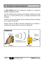
Страница 8: ...le r cepteur s effectue par ondes radio sur un canal particulier avec un codage personnalis code d identit La liaison radio est momentan e elle est seulement active lors de l appui sur un bouton de l...

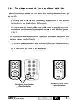
Страница 9: ...tion La commande d un relais Marche RM dans le r cepteur suivant mod le et uniquement si le r cepteur re oit l ordre de changement d tat En outre les metteurs quip s de ce bouton poss dent deux foncti...

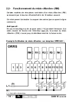
Страница 10: ...outon Marche Arr t de l metteur associ Ce relais permet de doubler la coupure des ordres par coupure de ligne commune Arr t passif En cas de brouillage ou de coupure radio 1s pendant l mission d un or...

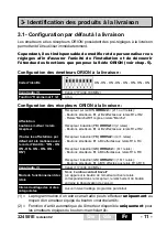
Страница 11: ...ur les metteurs quip s du bouton marche arr t Affectation boutons metteur relais r cepteur Toutes les affectations par d faut ont t r alis es avec le code d identit ON ON ON ON ON ON ON ON R cepteur s...

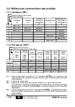
Страница 12: ...T ORRS42L1U 8 1 5 ORRA82L14 ORRA82L1A ORRA82L1B 16 1 5 ORRAH2L14 ORRAH2L1A ORRAH2L1B Nombre de relais de fonction Mod le de r cepteur tension d alimentation ORRD22L1C 3 2 R f rences commerciales des p...

Страница 13: ...OREL 1 OWE403 Planche de 64 tiquettes rondes pour metteur multifonctions OREL 12 ou 16 boutons 1 R f rence D signation OWR01 Kit antenne d brochable BNC voir installation du kit en annexe E 2 OWR02 K...

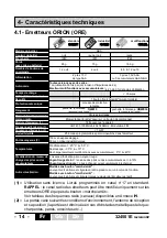
Страница 14: ...iel typique ABS 2 niveaux d indication par un voyant rouge Voyant rouge teint le niveau des piles ou des accumulateurs est 10 Voyant rouge clignote piles changer ou accumulateurs recharger Mod le sans...

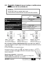
Страница 15: ...ni qu e Pour recharger l metteur ORION Multifonctions avec des accus veillez 1 Eteindre l metteur voyants rouge et vert teints appui sur le bouton marche arr t si pr sent 2 Poser l metteur sur le sup...

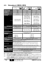
Страница 16: ...relais marche contr l par le bouton marche arr t de l metteur suivant mod le metteur cat gorie B selon EN 954 1 256 codes d identit possibles programmables par apprentissage de l metteur associ Avec...

Страница 17: ...mmutation pour relais marche et relais de fonction Commutation sous 230VAC 70VA cosphi 0 75 2 x 10 6 Commutation sous 110VAC 70VA cosphi 0 75 1 x 10 6 Commutation sous 48VAC 70VA cosphi 0 75 0 5 x 10...

Страница 18: ...A 250 VAC T F1 315 mA 250 VAC T F2 Carte aliment e en 230VAC 62 mA 250 VAC T F1 160 mA 250 VAC T F1 Relais de fonction Relais Marche Pas de protection Pas de protection R1 R2 R3 R4 R5 R6 R R13 R14 R15...

Страница 19: ...commande n 3 R3 bornier Alimentation bornier des contact du relais Marche R3 bornier des contact du relais R1 bornier des contact du relais R2 Microswitch JP4 Position de JP4 et comportement du relai...

Страница 20: ...pteur voir 5 4 Programmation des interverrouillages d ordres antagonistes voir 5 6 Programmation modification du canal de fr quence radio voir 5 7 Programmation modification de la temporisation pour l...

Страница 21: ...n 256 possibilit s L metteur ORE poss de un DIP switch de 8 curseurs 2 tats ON ou OFF afin de programmer le code d identit 5 2 Programmation du code d identit metteur Par d faut la livraison le code d...

Страница 22: ...t toute la proc dure 2 Pour les r cepteurs industriels ORRS et ORRA placer les cavaliers JP1 et JP3 en court circuit JP2 non court circuit pour le r cepteur ORRD placer les microswitchs JP1 et JP3 sur...

Страница 23: ...lors automatiquement les boutons de l metteur avec ses relais 6 Une fois cette programmation termin e les 2 voyants V2 et V3 s teignent mettre les r cepteurs type industriels ORRS et ORRA hors tension...

Страница 24: ...triel ORRA et ORRS le r cepteur sur rail DIN ORRD peut rester aliment durant toute la proc dure 2 Pour les r cepteurs industriels ORRS et ORRA placer le cavalier JP3 en court circuit JP1 et JP2 non co...

Страница 25: ...de bouton un code d identit son relais n 2 attente de 6 5s si aucun appui le r cepteur passe au relais n 2 Appuyer sur le bouton n 2 de l metteur par exemple dans un d lai de 6 5 secondes le r cepteur...

Страница 26: ...rche Arr t L tat du relais bistable est maintenu en cas d arr t de l metteur appui sur bouton Marche Arr t ou temporisation Homme mort coul e z Une association metteur r cepteur doit avoir t r alis e...

Страница 27: ...pe industriel ORRA et ORRS mettre le r cepteur sous tension 4 Les voyants V2 et V3 clignotent 3 fois puis s teignent 5 Appuyer et maintenir la pression environ 2 secondes avant de rel cher le bouton d...

Страница 28: ...ite un metteur et le r cepteur A chaque fois que le cavalier JP1 ORRS et ORRA est mis en court circuit ou que le microswitch JP1 ORRD est plac sur la position ON les interverrouillages pr c demment pr...

Страница 29: ...onctionnement bistable les ordres antagonistes ne sont pas forc ment mis simultan ment dans ce cas pr cis une priorit est donn e au dernier bouton appuy Exemple interverrouillage entre le bouton n 1 e...

Страница 30: ...17 434 700 MHz z Une association metteur r cepteur doit avoir t r alis e au pr alable z La proc dure de changement de canal radio se fait partir de l metteur et met en oeuvre les boutons B1 B2 et mar...

Страница 31: ...allum 10 teint 0 le voyant vert Vb indique les unit s par un nombre de clignotement Exemple Va est allum en continu et Vb clignote 7 fois s teint puis clignote 7 fois etc le canal radio actuel est 17...

Страница 32: ...pressiondes3boutons pendant1seconde Les voyants Va et Vb de l metteur sont allum s l metteur est en attente de choix du mode de programmation cette attente dure 4 secondes au del l metteur se met hors...

Страница 33: ...Annexe H r cepteurs ORRS r cepteurs ORRA r cepteur ORRD 3 R cepteur type industriel ORRA et ORRS mettre le r cepteur sous tension 4 Les voyants V2 et V3 indiquent le num ro de canal radio utilis actue...

Страница 34: ...re 2 Pour les r cepteurs industriels ORRS et ORRA placer les cavaliers JP1 JP2 et JP3 en court circuit pour le r cepteur ORRD placer les microswitchs JP1 JP2 et JP3 sur la position ON Seul le r glage...

Страница 35: ...du r cepteur Protection de l alimentation lectrique 6 1 Antiparasitage Lorsque des charges inductives sont raccord es aux sorties relais du r cepteur bobines de contacteurs lectrovannes ou lectrofrei...

Страница 36: ...qualit d utilisation d tre certain que le canal radio utilis est libre dans toute la zone o l appareil sera pilot Si plusieurs radiocommandes travaillent sur un m me site il convient d utiliser des f...

Страница 37: ...e ne doit pas tre plac e dans une enceinte formant un blindage armoire m tallique mur en b ton arm charpente ou paroi m tallique etc Tout obstacle situ entre l metteur et l antenne produit une diminut...

Страница 38: ...il est pr f rable d utiliser des embouts sertis afin d viter les faux contacts et courts circuits voir l annexe B pour le raccordement de l alimentation suivant les versions des r cepteurs 6 7 Recomm...

Страница 39: ...lisateur est attir e sur les risques de l utilisation de la t l commande dans un milieu comportant des solvants de polym res ou des colles pouvant d grader le bon fonctionnement des organes m caniques...

Страница 40: ...vis du bo tier et du presse toupe ORRA et ORRS ainsi que l tanch it de l antenne Si l accessoire OWR01 prise antenne BNC externe pour r cepteur industriels ORRA et ORRS est utilis v rifier le branchem...

Страница 41: ...ion inappropri e et permet un traitement et un recyclage des mat riaux qui le composent ce qui favorise des conomies importantes en terme d nergie et de ressources Les piles et accumulateurs contienne...

Страница 42: ...ent influences atmosph riques chimiques lectriques m caniques ou autres non appropri es ou non pr vues lors de la commande La garantie ne peut s exercer si des modifications d montages ou adjonctions...

Страница 43: ...De Installation and user technical manual R R R R Radio r adio r adio r adio r adio remote contr emote contr emote contr emote contr emote controls ols ols ols ols ORION Series ORION Series ORION Seri...

Страница 44: ...rger support p 55 4 3 ORR receivers p 56 4 3 1 Maximum number of simultaneously controlled relays p 57 4 3 2 Connection to relays p 57 4 3 3 Relay characteristics p 57 4 3 4 Protection of receiver boa...

Страница 45: ...mitters with accumulators and charger support p 76 6 6 Receiver and antenna positions p 77 6 7 Wiring recommendations p 78 6 7 1 Wiring the ORR receiver p 78 6 7 2 Wiring the electrical power supply o...

Страница 46: ...quency channel on some models duration of timing for Dead man function on some models z compact light weight watertight and sturdy transmitters and receivers z mechanical protection for buttons z on o...

Страница 47: ...ate machines by radio remote control z The operator must have uninterrupted visibility of the manoeuvre which he is performing When the operator s direct field of view is inadequate the controlled equ...

Страница 48: ...ecific channel with a customized code identity code The radio link is momentary it is only active when the button on the transmitter is pressed Each relay of the receiver can be programmed to ensure a...

Страница 49: ...n the function buttons Control an On relay RM in the receiver depending on model and only when the receiver receives the change of state command The transmitter models equipped with this button have t...

Страница 50: ...the associated transmitter These relays are used to double the cut out of the commands by cutting out the common line Passive shutdown In the event of jamming or of a radio cut out 1s while a command...

Страница 51: ...mitter button receiver relay association when transmitter button is pressed relay in the receiver is activated when button is no longer pressed the relay is deactivated Interlocking of conflicting com...

Страница 52: ...1 4 ORET41SL1 OREi41SL1 OREi42SL1 OREL42SL1 6 OREL62SL1 8 OREL81SL1 OREL82SL1 12 ORELD2SL1 16 ORELH1SL1 Transmitter model Number of function buttons 3 2 Product references 3 2 1 ORE transmitters 1 1 s...

Страница 53: ...3 64 black white round labels for multifunction transmitters 12 or 16 buttons 1 Reference Description OWR01 BNC plug in antenna kit see installation kit in appendix E 2 OWR02 Internal antenna kit see...

Страница 54: ...while the function button is pressed Model with On Off button A green indicator light come on and flashes when the transmitter keypad is active Momentary when command button pressed 256 codes program...

Страница 55: ...recharge the Multifunction transmitter with accumulators 1 Switch off the transmitter red and green indicator lights are OFF push on On Off button if present 2 Place the transmitter on the charger sup...

Страница 56: ...NC plug Tuner Sensitivity Temperature ranges Identity code Outputs Command type Response time Operating mode Interlocking Additional function ABS 1 red indicator light 1 4 wave fixed antenna 2 or inte...

Страница 57: ...spring terminals with connection points identified by numbers Flexible wires with wire section of between 0 08mm and 2 5mm can be used No common line is provided on the printed circuits all contacts...

Страница 58: ...oard supplied with 115VAC 100 mA 250 VAC T F1 315 mA 250 VAC T F2 Board supplied with 230VAC 62 mA 250 VAC T F1 160 mA 250 VAC T F1 Function relays On relay No protection No protection Against overcur...

Страница 59: ...smitters or the control relay No 3 function R3 Power supply connection On R3 relay connection R1 relay connection R2 relay connection JP4 Microswitch Position of JP4 and function of On R3 relay When m...

Страница 60: ...with receiver relays see para 5 4 Interlocking of conflicting commands programming procedure see 5 6 Radio channel programming procedure see 5 7 Dead man function time programming procedure see 5 8 P...

Страница 61: ...tion 256 possibilities The ORE transmitter is equipped with a 8 cursors 2 states DIP switch ON or OFF to program the identity code 5 2 Transmitter identity code programming By default in the delivery...

Страница 62: ...relay associations interlock functions and operating modes of the previously programmed relays only the radio channel setting is preserved The standard association procedure uses jumpers or microswitc...

Страница 63: ...r with the receiver The receiver affects then automatically the transmitter buttons with its relays 6 Once the programming procedure is finished 2 LEDs V2 and V3 go off switch off industrial receivers...

Страница 64: ...N rail ORRD can remain power supplied during all the procedure 2 For the ORRS and ORRA industrial receivers place jumper JP3 in the short circuit position JP1 and JP2 not short circuited for the ORRD...

Страница 65: ...itter button n 2 i e within 6 5 seconds The receiver records the assignment button n 2 identity code xxxxxxxx relay n 2 if no button is pressed within 6 5s the receiver selects the relay n X blinks X...

Страница 66: ...N position There are three operating modes for receiver function relays Mode 1 Continuous make contact The receiver relay remains closed so long as the corresponding control button on the transmitter...

Страница 67: ...and ORRS switch ON receivers 4 V2 and V3 LEDs blink 3 times then go off 5 Press and maintain the pressure approximately 2 seconds before releasing the transmitter button wich associated relays must h...

Страница 68: ...en realized z This procedure requires transmitter and receiver Every time JP1 jumper ORRS and ORRA is put in short circuit or JP1 microswitch ORRD is set on ON position previously programmed interlock...

Страница 69: ...that case a priority is given to the last pressed button Example interlocking between the button no 1 and the button no 2 in bistable relay operating mode An impulse on the button no 1 activates the r...

Страница 70: ...f button the radio frequency is fixed to nb 17 434 700 MHz z A transmitter receiver association must have been realized z This procedure is realized by the transmitter with buttons B1 B2 and on off z...

Страница 71: ...tes the units by flashing Example Va is light on and Vb flashes 7 times goes off then flashes 7 times etc the current radio channel number is 17 434 700MHz 5 Press B1 to increment the radio channel nu...

Страница 72: ...ns pressed for 1 second then release the 3 buttons Va et Vb transmitter LEDs come on steady The transmitter is waiting for a programming choice this waiting time lasts 4 seconds after the transmitter...

Страница 73: ...See list of available radio frequencies radio channels in appendix H ORRS receiver ORRA receiver ORRD receiver 3 Industrial type receivers ORRA and ORRS switch ON receivers 4 V2 and V3 LEDs indicate t...

Страница 74: ...ed during all the procedure 2 For the ORRS and ORRA industrial receivers place jumpers JP1 JP2 and JP3 in the short circuit position for the ORRD receiver set microswitches JP1 JP2 and JP3 to the ON p...

Страница 75: ...iver and associated systems Electrical power supply protection 6 1 Interference suppression In the event of inductive loads on the receiver relay outputs contactor coils solenoid valves or electro bra...

Страница 76: ...a system is used in continuous mode with the control buttons maintained pressed and the operator moving about transmission interruptions can occur due to the dispersion and propagation of radiowaves...

Страница 77: ...enclosure forming a shield metal cabinet wall made of reinforced concrete metal framework or wall etc Any obstacle located between the transmitter and the antenna will result in a loss of range Insofa...

Страница 78: ...Wiring recommendations Generalities Do not place cables of different classes side by side A minimum space 20 cm should be observed between the different classes Class 1 Radio antenna cable case of an...

Страница 79: ...ransmitter The attention of the user is attracted to the risks of the use of the remote control in an environment containing solvents of polymers or glues which can degrade the good functioning of tra...

Страница 80: ...tightening of screws and cable glands ORRS and ORRA and tightness of antenna If accessory OWR01 external BNC antenna connector for ORRA and ORRS receiver is used check the antenna connection and check...

Страница 81: ...riate elimination of electronic waste and will allow proper processing and recycling of the materials forming the unit representing significant savings in terms of energy and resources Batteries and s...

Страница 82: ...hemical electrical or other conditions Conditions not specified on order of the equipment The warranty shall not apply subsequent to any modifications or additions to the equipment performed by the cu...

Страница 83: ...evision02 83 De Technische Notiz und Benutzerhandbuch Funkf Funkf Funkf Funkf Funkfer er er er ernsteuer nsteuer nsteuer nsteuer nsteuerung ung ung ung ung Serie ORION Serie ORION Serie ORION Serie OR...

Страница 84: ...s 95 4 3 Empf nger ORR s 96 4 3 1 H chstzahl gleichzeitig steuerbarer Relais s 97 4 3 2 Relaisanschlu s 97 4 3 3 Eigenschaften der Relais s 97 4 3 4 Schutz der Empf ngerkarte und der Relais s 98 4 3...

Страница 85: ...enutzung s 116 6 6 PositionvonEmpf ngerundAntenne AuswahldesTypsvonAntenne s 117 6 7 Empfehlungen ber die Kabelverlegung s 118 6 7 1 Verkabelung des Empf ngers ORR s 118 6 7 2 Verkabelung der elektron...

Страница 86: ...ellen Programmierung der Zeitverz gerung f r die Totmann Funktion bei einigen Modellen z Kompakte und leichte Sender und Empf nger z Mechanischer Tastenschutz z Ein Aus Taste bei einigen Modellen Dies...

Страница 87: ...die von ihm durchgef hrten Man ver behalten Wenn das direkte Sichtfeld des Bedieners unzureichend ist m ssen die Hebeger te mit zus tzlichen Vorrichtungen zur Verbesserung der Sichtbarkeit ausgestatt...

Страница 88: ...uf einem besonderen Kanal mit individueller Verschl sselung Identit tscode Die Funkverbindung wird momentan erstellt und ist nur bei der Bet tigung einer Sendertaste aktiv Jedes Empf ngerrelais kann f...

Страница 89: ...er der Funktionstasten Die Steuerung des Relais Ein RM im Empf nger je nach Modell und nur wenn der Empf nger einen Status nderungsbefehl empf ngt Des weiteren besitzen mit dieser Taste ausger stete S...

Страница 90: ...en Senders gesteuert wird Mit diesem Relais kann die Befehlsunterbrechung verdoppelt werden durch Unterbrechung der gemeinsamen Leitung Passive Abschaltung Bei St rung oder Funkunterbrechung 1 s w hre...

Страница 91: ...das entsprechende Empf ngerrelais aktiviert Bei Loslassen der Taste wird das Relais deaktiviert Zwischenverriegelung gegens tzlicher Man ver Keine programmierte Standard Zwischenverriegelung Identit t...

Страница 92: ...ifunktions Versionen Ein Aus 3 1 ORET11SL1 2 ORET21SL1 OREi21SL1 OREi22SL1 4 ORET41SL1 OREi41SL1 OREi42SL1 OREL42SL1 6 OREL62SL1 8 OREL81SL1 OREL82SL1 12 ORELD2SL1 16 ORELH1SL1 Sender Modell Anzahl Fu...

Страница 93: ...Tasten 1 Referenz Bezeichnung OWR01 Abnehmbare Antenne BNC Kit Siehe Installation im Anhang E 2 OWR02 Inneres Antenne Kit Siehe Installation im Anhang F 3 VUB084 Gerade 1 4 Welle Antenne BNC 4 VUB086...

Страница 94: ...50 m in industriellem Umfeld ABS 2 Anzeigeniveaus durch eine rote LED Rote LED aus Batterien Akkus ladung als 10 Rote LED blinkt Batterien m ssen ersetzt werden oder Akkus m ssen aufgeladen werden Mod...

Страница 95: ...Akkus folgendes beachten 1 1 Sender ausschalten rote und gr ne Konrollleuchte aus Druck auf die Ein Aus Taste falls vorhanden 2 2 Sender auf die Ladehalterung setzen W hrend des Ladevorgangs leuchtet...

Страница 96: ...2 VDC 9 bis 20VDC 24 VDC 20 bis 75VDC 24 VAC 10 15 48 VAC 10 15 Modell ORRS T 115 VAC 10 15 Modell ORRS U 230 VAC 10 15 auf Schaltplatine aufgeschrautbte Reihenklemme f r 2 5 mm Kabel ABS 1 Rote LED E...

Страница 97: ...4 3 3 Eigenschaften der Relais Relais Ein und Funktionsrelais 4 3 1 H chstzahl gleichzeitig steuerbarer Relais je nach industriellem Empf ngermodell Anzahl der Umschaltungen der einzelnen Sch tze Die...

Страница 98: ...Karte 100 mA 250 VAC T F1 315 mA 250 VAC T F2 Mit 230 VAC gespeiste Karte 62 mA 250 VAC T F1 160 mA 250 VAC T F1 Funktionsrelais Relais Ein Kein Schutz Kein Schutz Industrielle Empf nger kleines Model...

Страница 99: ...ssklemme Relais R1 Anschlussklemmen Stromversorgung Anschlussklemme Relais Ein R3 Anschlussklemme Relais R2 Mikroschalter JP4 Der ORRD Empf nger auf DIN Schienen besitzt ein Relais Ein R3 dessen Funkt...

Страница 100: ...rtasten und Empf ngerrelais siehe 5 4 Befehlsablauf gegenwirkender Befehle programmieren Zwischenverriegelung siehe 5 6 Funkfrequenzkanal programmieren ndern siehe 5 7 Zeitverz gerung Totmann Funktion...

Страница 101: ...erung des Identit tscodes einen DIP Switch mit 8 Cursors auf 2 m glichen Positionen ON oder OFF 5 2 Programmierung des Identit tscodes Bei der Lieferung ist der Identit tscode werksm ig folgenderma en...

Страница 102: ...Programmierverfahren werden alle vorher programmierten Tasten Relais Zuordnungen Tastenkombinationen und Relaisfunktionsweisen gel scht lediglich die Einstellung des Funkkanals wird beibehalten WICHT...

Страница 103: ...r Empf nger ordnet die Sendertasten automatisch seinen Relais zu 6 Nach Beendigung dieser Programmation die beiden LEDs V2 und V3 erl schen die industriellen Empf nger Bauart ORRS und ORRA ausshalten...

Страница 104: ...Nach erfolgreicher Programmierung des Identit tscodes auf den Sender m ssen die Empf ngerrelais den Sendertasten zugeordnet werden 5 4 Individuelle Zuordnung der Sendertasten und Empf ngerrelais 1 Di...

Страница 105: ...d leuchten durchgehend auf Der Empf nger wartet auf den Befehl des Senders zum Starten des Zuordnungsverfahrens Tasten Relais Auf eine der Funktionstasten des Senders dr cken und loslassen erlischt da...

Страница 106: ...nders Druck auf die Ein Aus Taste oder Ablauf der Totmannzeit aufrecht erhalten JP1 JP4 V1 V3 V2 JP3 JP2 ON OFF V1 V2 V3 JP1 JP3 JP2 V1 V2 V3 JP1 JP2 JP3 Empf nger ORRS Empf nger ORRA Empf nger ORRD z...

Страница 107: ...ten 4 Die Kontrollleuchten V2 und V3 blinken 3 Mal und erl schen dann 5 Die Funktionstaste des Senders dessen zugeordnete Relais mit einer Funktionsweise programmiert werden sollen dr cken und den Dru...

Страница 108: ...wenn der Jumper JP1 ORRS und ORRA kurzgeschlossen oder der Microswitch JP1 ORRD auf die Position ON gestellt wird werden die vorher programmierten Befehlsabl ufe gel scht 5 6 Programmierung der Zwisc...

Страница 109: ...s R3 m glich aber nicht zwischen R1 und R6 Die Programmierung der Zwischenverriegelung dieses Empf ngers kann nur mit Relais derselben Gruppe erfolgen 5 6 2 Besonderheit des industriellen Empf ngers g...

Страница 110: ...ht ge ndert werden Nr 17 434 700 MHz z Die Zuordnung von Sender und Empf nger muss im Vorfeld durchgef hrt worden sein z Das nderungsverfahren des Funkkanals erfolgt mit dem Sender und ben tigt den Ei...

Страница 111: ...gr ne Kontrollleuchte Vb gibt die Einer durch Blinken an Beispiel Va leuchtet durchgehend und Vb leuchtet 7 mal auf und erlischt Leuchtet noch einmal 7 mal auf und erlischt etc Der derzeitige Funkkana...

Страница 112: ...nde lang gedr ckt halten Die Kontrollleuchten Va und Vb des Senders leuchten der Sender erwartet die Wahl des Programmiermodus die Wartestellung dauert 4 Sekunden Dar ber hinaus schaltet sich der Send...

Страница 113: ...f nger ORRD 3 Industrielle Empf nger ORRA und ORRS Empf nger einschalten 4 Die Kontrollleuchten V2 und V3 geben die Nummer des derzeitig vom Empf nger benutzten Funkkanals an V2 gibt die Zehner an ein...

Страница 114: ...ngern ORRS und ORRA die Jumper JP1 JP2 und JP3 kurzschlie en beim ORRD Empf nger die Microswitch JP1 JP2 und JP3 auf ON stellen Einzig die Einstellung des Funkkanals wird beibehalten 3 Industrielle Em...

Страница 115: ...f den Automateneng ngen zu benutzen Beispiele f r zu benutzende Schutzvorrichtungen Die Erfahrung hat gezeigt da das Betriebsergebnis einzig von einer sorgf ltigen Installation abh ngt Entst rung Ausw...

Страница 116: ...es wichtig sicherzugehen dass der benutzte Funkkanal in der gesamten Zone innerhalb derer die Ausr stung gesteuert wird frei ist Wenn mehrere Funkfernsteuerungen auf dem gleichen Standort betrieben w...

Страница 117: ...ren darf die Antenne nicht an abgeschirmten Orten aufgestellt werden Metallschrank Mauer aus Stahlbeton Metalldach oder wand usw Jegliches Hindernis zwischen Sender und Antenne verringert die Reichwei...

Страница 118: ...20 cm zwischen den unterschiedlichen Klassen einhalten Klasse 1 Funk Antennenkabel Antennenverl ngerung Klasse 2 Stromnetz f r Energieversorgung der einzelnen Geh use Klasse 3 Leistungssteuerung der...

Страница 119: ...es Benutzers wird auf die Einsatzrisiken der Fernsteuerung in Umgebungen mit polymerhaltigen L sungsmitteln oder Klebstoffen gelenkt die das ordnungsgem e Funktionieren der mechanischen Bestandteile d...

Страница 120: ...g Zustand der Deckeldichtung Sitz der Schrauben und PG Verschraubungen ORRS und ORRA sowie Antennendichtigkeit Wenn das Zubeh r OWR01 externer Antennenstecker BNC benutzt wird Anschluss der Antenne pr...

Страница 121: ...g enstehen k nnen und erm glicht die Aufarbeitung der Bestandteile wodurch bedeutende Einsparungen von Energie und Ressourcen erzielt werden k nnen Batterien und Akkus enthalten giftige und umweltsch...

Страница 122: ...gesehene Lager Betriebs oder Umweltbedingungen atmosph rische chemische elektrische oder andere Einwirkungen zur ckzuf hren sind Die Garantie entf llt wenn der Kunde Ver nderungen oder Erg nzungen am...

Страница 123: ...Gb De 324501E revision02 123 Fr Annexes Appendix Anhang...

Страница 124: ...r la programmation du code d identit English A Location of function labels B Function buttons C Red LED Va Battery level radio channel indic tens D Green LED Vb function button pressed or transmitter...

Страница 125: ...2 3 1 2 3 1 2 3 1 2 3 1 2 3 ORRS L1F ORRS L1T ORRS L1U 12 24 VDC 1 24 VAC ORRD22L1C 1 2 JP2 JP3 JP1 OFF ON 1 2 3 4 1 2 3 1 2 3 Annexe Appendix Anhang B ORRA ORRS ORRD Raccordement de l alimentation s...

Страница 126: ...V2 V3 E RM R1 R2 R3 R4 R5 R6 R7 R8 R9 R10 R11 R12 R13 R14 R15 R16 4 5 6 7 8 9 10 11 12 13 14 15 16 17 18 19 20 21 22 23 24 25 26 27 28 29 F1 F2 C1 B i H V1 V3 V2 D 5 7 6 8 1 3 2 4 JP2 JP3 JP4 JP1 OFF...

Страница 127: ...teur Rx Relais de commande le nombre de relais diff re suivant la version du r cepteur ORR H Bornier Alimentation i Borniers des contacts des relais de commande English A Cable gland Power supply Cont...

Страница 128: ...ronique 85 56 31 24 6 114 77 lectronique Emetteur multifonctions OREL OREL OREL OREL OREL Multifunction transmitter OREL OREL OREL OREL OREL Multifunktions Sender OREL OREL OREL OREL OREL Supports cha...

Страница 129: ...ORRA ORRA ORRA Industrial receiver large model ORRA ORRA ORRA ORRA ORRA Industrielle Empf nger gro es Modell ORRA ORRA ORRA ORRA ORRA R cepteur industriel petit mod le ORRS ORRS ORRS ORRS ORRS Industr...

Страница 130: ...lectronique R cepteur Receiver Empf nger ORRA lectronique Annexe Appendix Anhang E R cepteur Receiver Empf nger ORRS OWR01 Kit antenne externe External antenna kit Abnehmbare Antenne BNC Kit 1 2 3 4...

Страница 131: ...Fr lectronique R cepteur Receiver Empf nger ORRA lectronique Annexe Appendix Anhang F R cepteur Receiver Empf nger ORRS 1 2 3 4 1 2 3 4 OWR02 A B C A B C A B C OWR02 Kit antenne interne Internal ante...

Страница 132: ...endix Anhang G 5mm PZ1 5mm OWE10 Clip d accrochage Carrying clip Trageclip g c d e f vue int rieur couvercle internal cover view Innenansicht Deckel OWE10 A B OREI ORET OREL A B vue ext rieur couvercl...

Страница 133: ...labstand 0 100MHz Canal Channel Kanal Fr quence Frequency Frequenz MHz Canal Channel Kanal Fr quence Frequency Frequenz MHz 01 433 100 10 434 000 02 433 200 11 434 100 03 433 300 12 434 200 04 433 400...

Страница 134: ...134 324501E revision02...

Страница 135: ...Postleitzahl Tel Fax E mail Page Seite ___ Page Seite ___ Page Seite ___ Page Seite ___ Page Seite ___ Am liorons ensemble ce manuel d installation et d utilisation We can improve this manual with you...

Страница 136: ...136 324501E revision02...

Страница 137: ...324501E revision02 137 NOTES...

Страница 138: ...138 324501E revision02 NOTES...

Страница 139: ...324501E revision02 139...

Страница 140: ...ZAC la B tie rue Champrond F38334 SAINT ISMIER cedex 33 0 4 76 41 44 00 33 0 4 76 41 44 44 www jay electronique fr lectronique Realisation JAY Electronique 234501E revision02 FED P65 21 05 08 ED...

Отзывы: