- 84 -
ISIS
- 331260D
revision02
FR
DE
EN
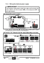
The electrical connections should be made such that when the
main switch is off, the receiver
ISR
or the transceiver
IST
is
also deactivated.
IMPORTANT
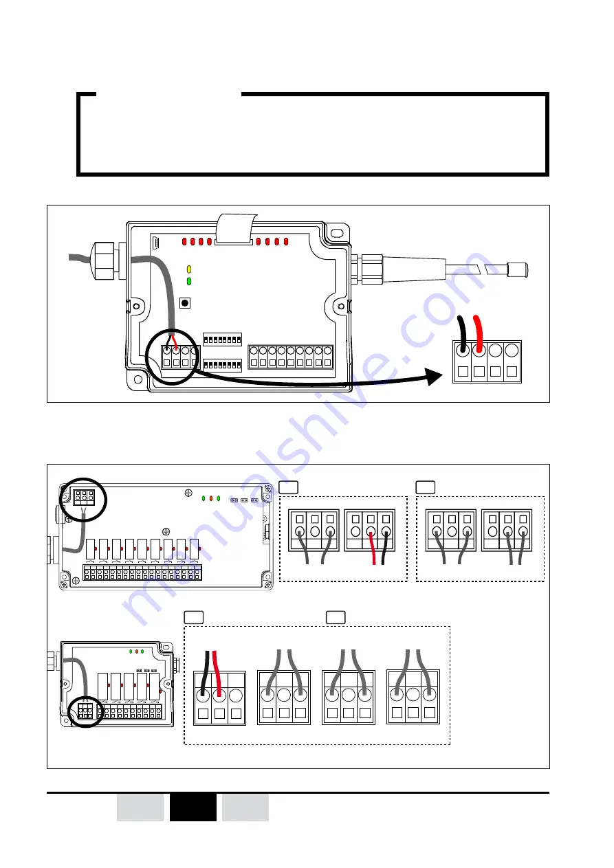
7.3.3- Wiring the electrical power supply
ISE
transmitter power supply * :
1 2
ON
3 4 5 6 7 8
1 2
ON
3 4 5 6 7 8
+
-
DC
A
Vb
S1
Va
CONFIG
ID
C 1
i1 i2 i3 i4
i5 i6 i7 i8
2 3 4 5 6 7 8
B
+
+
-
-
DC
A
9 à 30Volts
DC
B
ISR
receiver /
IST
Transceiver power supply (depending on version) :
V2
JP1
RM
R1
R2
R3
R4
JP2 JP3
V1
V3
4 5 6 7 8 9 10 11 12 13
1 2 3
1 2 3
1 2 3
1 2 3
1 2 3
JP1
4 5 6 7 8 9 10 11 12 13
16 17 18 19 20 21
14 15
RM
R1
R2
R3
R4
R5
R6
R7
R8
V2
V1
V3
JP2 JP3
24 VDC
(1)
12 VDC
48 VAC
24 VAC
1
2
3
1 2 3
1 2 3
1 2 3
1 2 3
+
-
1
2
3
1
2
3
24 VDC
(1)
12 VDC
3
2
1
3
2
1
+
-
1
2
3
1
2
3
48 VAC
24 VAC
3
2
1
3
2
1
,65$
4 /
,67$
4
,656)
DC
DC
,65$
A /
,67$
A
AC
AC
Receiver
ISRA
or transceiver
IST
Receiver
ISRS
(1) = no polarity to be respected
9 to 30V
DC
*
= In the case of a transceiver
IST
, the transmitter module power supply is
provided by the receiver module of the transceiver..
Содержание ISIS Series
Страница 2: ...2 ISIS 331260D revision02...
Страница 52: ...52 ISIS 331260D revision02 FR DE EN...
Страница 102: ...102 ISIS 331260D revision02 FR DE EN...
Страница 153: ...153 ISIS 331260D revision02...
Страница 154: ...154 ISIS 331260D revision02 NOTES...
Страница 155: ...155 ISIS 331260D revision02...

