- 60 -
ISIS
- 331260D
revision02
FR
DE
EN
4 5 6 7 8 9 10 11 12 13
16 17 18 19 20 21
14 15
RM
R1
R2
R3
R4
R5
R6
R7
R8
1
2
3
A
B
1 2
ON
3 4 5 6 7 8
1 2
ON
3 4 5 6 7 8
+
-
DC
A
CONFIG
ID
C 1
i2
i1
i3 i4
i5 i6 i7 i8
2 3 4 5 6 7 8
B
i1...i8
Set
F1
A
ID
CFG
B
Va
Vb
F1
F2
V2 V3
V1
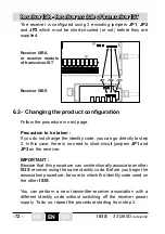
JP1 JP2 JP3
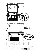
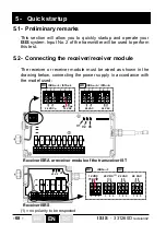
«8 relay outputs receiver» Module
V1
Green indicator light «power supply»
JP1
Jumper «JP1»
V2
Red indicator light «programming»
JP2
Jumper «JP2»
V3
Green indicator light «radio reception»
JP3
Jumper «JP3»
F1
Fuse (see chapter 11.4)
A
Term.strip «Power supply»
F2
Fuse (see chapter 11.4)
B
Term.strip «Relay outputs»
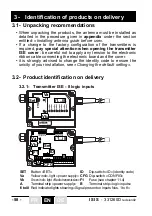
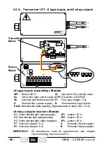
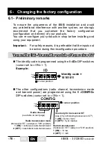
«8 logic inputs transmitter» Module
SET
Button «SET»
ID
Dip-switch «ID» (identity code)
Va
Yellow indic. light «power supply»
CFG
Dip-switch «CONFIG»
Vb
Green indic. light «Radio transmission»
F1
Fuse (see chapter 11.4)
A
Terminal strip «power supply»
B
Terminal strip «logic inputs»
i1 to i8
Red indicator lights showing «Signal present on inputs Nos. 1 to 8»
IMPORTANT :
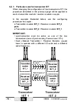
All transceivers must be synchronized, see chapter
«Synchronizing Transceivers IST»
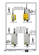
Transmitter
Module
Receiver
Module
3.2.4- Transceiver
IST
- 8 logic inputs and 8 relay outputs
Содержание ISIS Series
Страница 2: ...2 ISIS 331260D revision02...
Страница 52: ...52 ISIS 331260D revision02 FR DE EN...
Страница 102: ...102 ISIS 331260D revision02 FR DE EN...
Страница 153: ...153 ISIS 331260D revision02...
Страница 154: ...154 ISIS 331260D revision02 NOTES...
Страница 155: ...155 ISIS 331260D revision02...

