14
5
Failure
indicator
Light up when there is any failure.
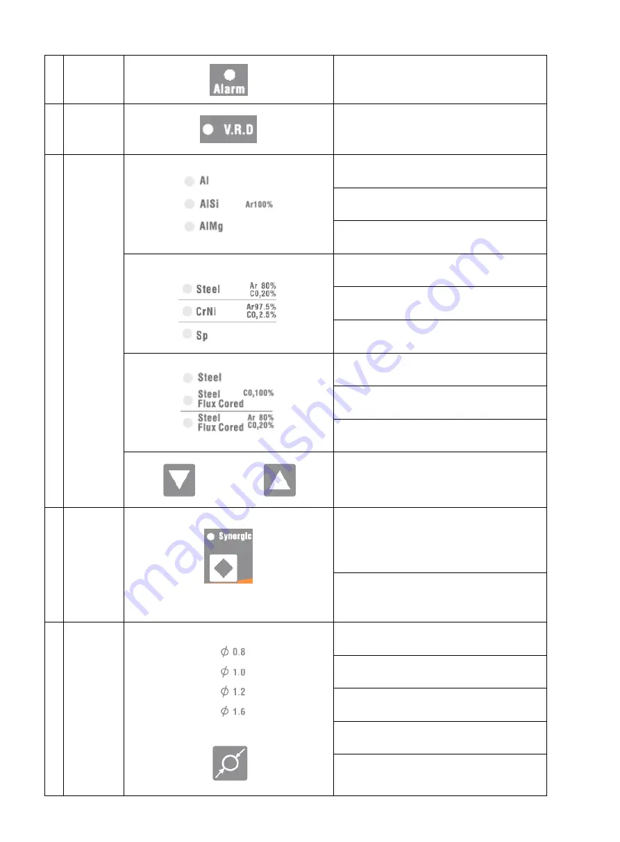
6
VRD
indicator
MMA unload status output voltage indicator.
Green means safe; red means danger.
7
Wire
&
Gas
selection
area
○
,1
Al + Ar100%
○
,2
AlSi + Ar100%
○
,3
AlMg + Ar100%
○
,1
Steel + Ar80%CO
2
20%
○
,2
CrNi + Ar97.5%CO
2
2.5%
○
,3
SP1
○
,1
Steel + CO
2
100%
○
,2
Steel Flux-Cored + CO
2
100%
○
,3
Steel Flux-Cored + Ar80%CO
2
20%
welding method selection key K5
、
K6
8
Synergy
○
,1
Synergic status indicator: light on means
under synergy control. Light off means
“separate”
○
,2
“synergy”
、
“separate” status switch key
K7
9
Wire
diameter
selection
area
○
,1
Φ0.8
○
,2
Φ1.0
○
,3
Φ1.2
○
,4
Φ1.6
○
,5
wire diameter selection key K7
①
②
③
①
②
③
①
②
③
①
②
①
②
③
④
⑤
Содержание MIG 350P
Страница 13: ...11 4 6 2 Separated machine installation Figure 4 3 ...
Страница 19: ...17 3 Operation modes Table 5 2 DC MIG operation modes Modes Sketch map 2T 4T ...
Страница 20: ...18 Repeat Spot weldin g 5 2 3 Pulse MIG 1 Synergic and Separate ...
Страница 22: ...20 2T with initial crater 4T ...
Страница 23: ...21 4T with initial segmen t Special 4T pro gram 4T ...
Страница 40: ...38 7 Wiring Diagram ...
Страница 42: ...40 ...


