32
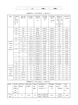
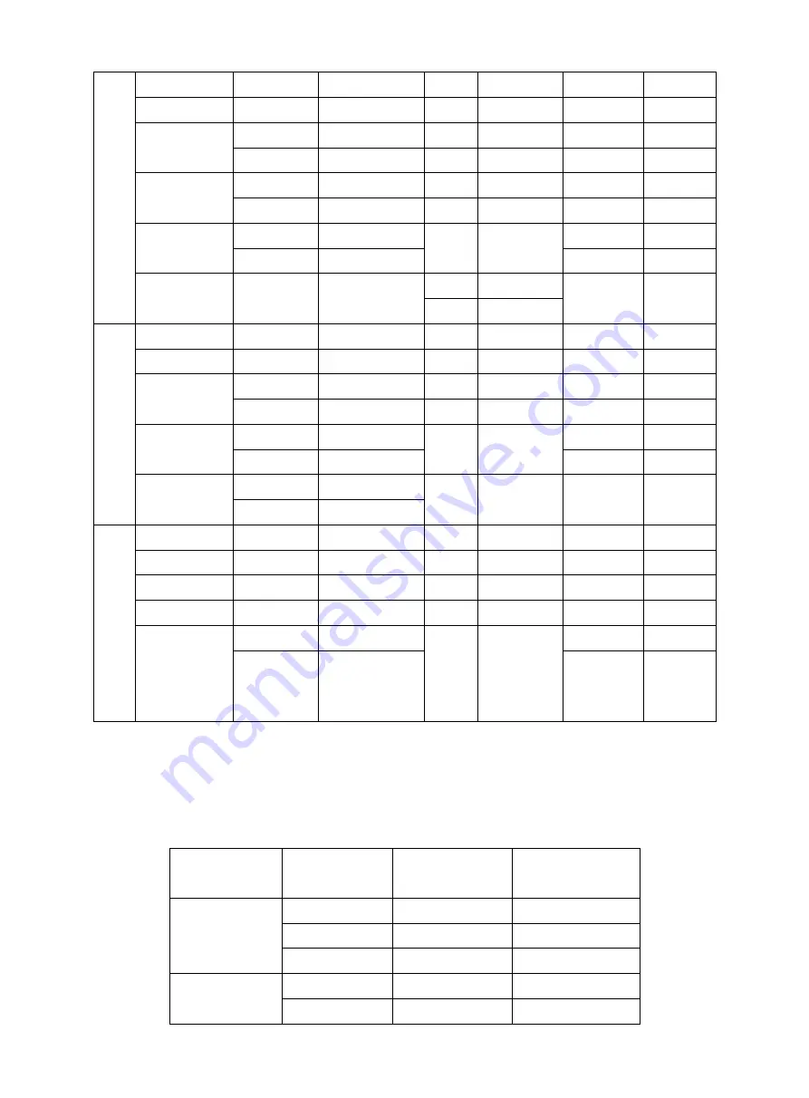
Fillet
weld
in
the
horiz
ontal
posit
ion
2
2
55-65
~
~
3
3.2
100
~
120
~
~
4
3.2
100
~
120
~
~
4
160
~
200
~
~
5
~
6
4
160
~
200
~
~
5
220
~
280
~
~
≥7
4
160
~
200
5
220
~
230
5
220
~
280
~
4
160
~
200
4
160
~
200
4
160
~
220
5
220
~
280
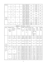
Fillet
weld
in
the
verti
cal
posit
ion
2
2
50
~
60
~
~
3
~
4
3.2
90
~
120
~
~
5
~
8
3.2
90
~
120
~
~
4
120
~
160
9
~
12
3.2
90
~
120
4
120
~
160
4
12
~
0160
~
3.2
90
~
120
4
120
~
160
3.2
90
~
120
4
120
~
160
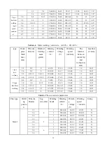
Fillet
weld
in
the
over
head
posit
ion
2
2
50
~
60
~
~
3
~
4
3.2
90
~
120
~
~
5
~
6
4
120
~
160
~
~
≥7
4
140
~
160
4
140
~
160
~
3.2
90
~
120
4
140
~
160
3.2
90
~
120
4
14
~
0160
4
140
~
160
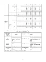
6.4.2 MIG processing parameters
Table 6-4 CO
2
welding nozzle distance and gas flow
Wire
diameter/mm
Welding
current/A
Nozzle
distance/mm
Gas flow L/min
1.2
100
10
~
15
15
~
20
200
15
20
300
20-25
20
1.6
300
20
20
350
20
20
Содержание MIG 350P
Страница 13: ...11 4 6 2 Separated machine installation Figure 4 3 ...
Страница 19: ...17 3 Operation modes Table 5 2 DC MIG operation modes Modes Sketch map 2T 4T ...
Страница 20: ...18 Repeat Spot weldin g 5 2 3 Pulse MIG 1 Synergic and Separate ...
Страница 22: ...20 2T with initial crater 4T ...
Страница 23: ...21 4T with initial segmen t Special 4T pro gram 4T ...
Страница 40: ...38 7 Wiring Diagram ...
Страница 42: ...40 ...


