


78
Default value 0
.
5
Constant
-
speed torque limiting time
P429
Setting Range
:
0
~
999
.
9S Unit
:
0
.
1
Default value 0
P430
Setting Range
:
0
~
2
.
00S Unit
:
0
.
1
This parameter sets frequency reached width
,
for details
,
refer to P425
-
F426
introductions
Width of arrive of frequency in hqsteretic loop
.
5
Default value 0
Default value 0
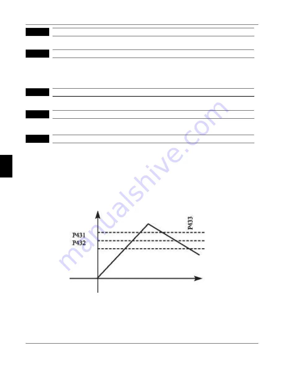
Jump Frequency 1
Jump Frequency 2
P431
Setting Range
:
0
~
frequency upper limit Unit
:
0
.
1
Setting Range
:
0
~
frequency upper limit Unit
:
0
.
1
P432
Default value 0
.
5
Jump frequency hysteresis loop width
Setting Range
:
0
~
2
.
0 Unit
:
0
.
1
If machine resonance occurred at a certain frequency
,
we can use the
frequency jump function to skip the resonance point
.
t
!
20OtJ support 2 jump
frequencies by parameter P431 and P432
.
Frequency jump hysteresis loop width can be set through P433 as below
:
P433
6
Chapter 6 Description of parameter setting
FC100 Series User Manaul
Содержание FC100 Series
Страница 9: ...9 Chapter 2 Storage and Installation ...
Страница 12: ...12 ...
Страница 13: ...13 Chapter 3 Wiring Diagram and Terminal Explanation ...
Страница 20: ...20 ...
Страница 21: ...21 Chapter 4 Keypad Operation ...
Страница 24: ...24 4 ...
Страница 25: ...25 Chapter 5 Function Parameters Table ...
Страница 36: ...36 ...
Страница 37: ...37 Chapter 6 DESCRIPTION OF PARAMETER SETTINGS ...
Страница 99: ...Chapter 7 Maintence and Inspection 99 ...
Страница 108: ...Noise reduction examples 8 108 Chapter 8 Troubleshooting and Fault Informatin FC100 Series User Manaul ...


