1.3
Adjusting of the setting gauge
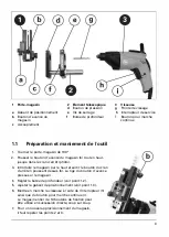
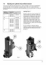
The edge clearance for the respective glass mouldings is set using the setting gauge. For this
setting the glass moulding is on the room side, flush with the frame. With the clamping bolt (r)
and without the locking bolt, other different edge clearances can be set.
Edge
Glazing beads
clearance
Steel
7
402.015 Z
402.112 Z
5,7
9
402.115 Z
402.120 Z
402.125 Z
402.130 Z
402.215 Z
402.220 Z
18
402.135 Z
402.140 Z
Aluminum
404.112
404.109
404.015
404.115
404.116
404.118
404.120
404.125
404.129
404.130
404.135
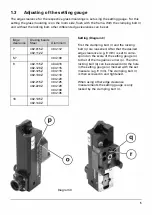
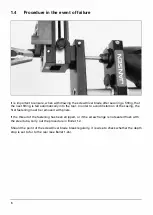
Diagram 3
Setting (Diagram 3)
First the clamping bolt (r) and the locking
bolt (q) are loosened. After that the desired
edge clearance (e.g. 9 mm) is set to corre
spond on the scale of the setting gauge (o)
to that of the magazine carrier (p). Then the
locking bolt (q) can be screwed into the hole
in the setting gauge (o) marked with the set
measure (e.g. 9 mm). The clamping bolt (r)
is then screwed in and tightened.
When using other edge clearance
measurements the setting gauge is only
locked by the clamping bolt (r).
5

