


Page 10
3. Remove the two screws holding the bezel in
place. Turn the bezel over to view the circuit
board on the back.
4. Locate the programmed chip on the Power
Center Board (the larger square chip in the
lower right corner of the circuit board). In the
center of the chip is the revision letter. If the
revision letter is "H" or higher go to step 5. If
the revision level is "G" or lower, replace the
chip. Directions for removal and installation of
the chip are provided in the new PPD Kit .
NOTE:
If ordering a new programmed chip, be sure to
order the part number printed on the chip
currently in your RS control .
5. Use 22 gauge 4-conductor wire (WP/J part #
4278) to run between the heater and the RS
control, and match the wire color order.
6. The wires coming from the LX heater can be
doubled up on the red terminal bar with the
four wires coming from the indoor controller.
NOTE:
If you need to install more than two wires in
each terminal, order a Waterpik Technologies/
Jandy Multiplex PCB Kit, which includes the
Multiplex Board (WP/J part # 6584). Never put
more than two wires into each of the pins of the
terminal bar.
7. On the heater's electronic control board, verify
that the water temperature sensor is connected
(J4), and that jumper is in place on W0.
8. Check all wiring, then apply power to both the
heater and the RS control system. Operation can
be verified in either Service or Auto mode. See
your RS Control System for instructions about
operation.
When the LX heater is first powered, the display on
the control will show "RS ONLINE". If there is an RS
control connected to the heater, it will sense the RS unit
and remain online. When the display shows "RS
ONLINE" all functionality of the control on the heater is
disabled. The heater functions can be controlled only at the
RS unit. However, sensor data is displayed at both the
heater and the RS unit.
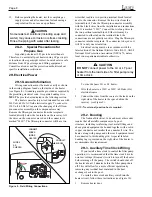
To temporarily use the heater controls, use a thin
object to depress the button marked "RS SERVICE". The
"RS ONLINE" indicator will disappear from the heater
display. All functionality has now been returned to the
control on the heater. In this mode the RS unit has been
disabled. To return the functionality to the RS unit, push
the button again.
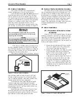
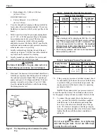
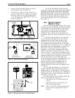
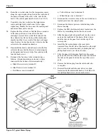
An interrupt (on/off) type remote can be connected
by removing the jumper wire on the terminal block located
in the control compartment (see Figure 8) and connecting
the two wires from the remote to the two terminals on the
terminal block. This type of remote control will turn the
heater on or off, but will not perform any other function.
Consult with Waterpik Technologies Service
Department with questions about installing remote
controls manufactured by companies other than Waterpik
Technologies.
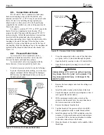
2I. Water Piping
2I-1. Reversal of Heater Water
Connections
The LX and LT are shipped with water connections
on the right side, but they can be modified in the field to
provide left-side water connections. This procedure
involves removing the heat exchanger and reinstalling it
opposite to it's original position. Some of the heater wiring
and control components must be relocated, so this
procedure must be done only by a trained service
technician.
Heat exchanger reversals are generally done before
the installation of power and water to the heater. If you
need to reverse the heat exchanger on a previously
installed heater be sure that all electrical power and water
supply has been turned off before starting the procedure.
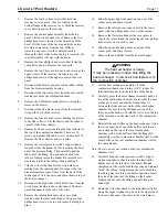
Water connection reversal is illustrated in Figures 13 and
14. Proceed as follows:
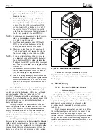
1.
Remove the heater front panel (door).
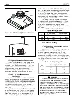
Figure 13. Water Connection as Shipped.
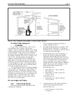
Figure 14. Water Connection Reversed.