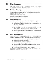
Dimmer Operation
10
Revision 2.0c – 30 August 2013
HPC User Manual
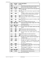
First
Level
Second
Level
Third
Level
Description
Chn
Use channel select buttons drive channel/s to full
n-E On-off
When ON the N-E fault detector is enabled
SIG
no.S
HLd
Set the HPC to hold the current output upon loss
of DMX data
SIG
no.S
Sc.1
Set the HPC to fade to Scene 1 upon loss of DMX
data
SIG
End
Toggle the DMX terminate function. The TERM LED
indicates when the terminate function is active.
SIG
Src
D d
Level and RDM via DMX connector
SIG
Src
D e
Level via DMX connector and RDM via Ethernet
connector
SIG
Src
E D
Level via Ethernet connector and RDM via DMX
connector
SIG
Src
E e
Level and RDM via Ethernet connector
CAP 240-100
Cap the maximum output voltage. 240 = 240V
nominal operation.
Pre OFF-50
Set the Preheat level
Rlc
byp
---
Some channels have Bypass enabled and some
don’t
Rlc
Byp
On
Relay bypass will automatically activate
Rlc
Byp
Off
Relay bypass will not automatically activate
Rlc
iso
---
Some channels have Isolate enabled and some
don’t
rlc
Iso
On
Relay Isolate will automatically activate
rlc
iso
Off
Relay Isolate will not automatically activate
Chc
24.C
Display the internal measured temperature in
degrees Celsius
CHC
D.21
Display the DMX packet rate (per second)
Chc
3.PH
Display the number of connected phases. Note
that 2.PH is displayed when 1 or 2 phase power is
connected.
Chc
50.H
Display the mains frequency
Scn
SC1
Press MENU/
to play Scene 1. Press and hold
MENU/
to record Scene 1.
Scn
SC2
Press MENU/
to play Scene 2. Press and hold
MENU/
to record Scene 2.
CHS SP1-SP9
Activate the chase and set the rate
ALL
0-FL
Drive all channels in 10% increments
Table 2: Menu Function Reference
Содержание HPC AIRGAP
Страница 1: ...HPC ...


