Dimmer Operation
11
Revision 2.0c – 30 August 2013
HPC User Manual
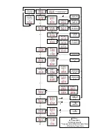
5.1.2 Cap Function
The Cap function is used to scale the output voltage of all channels from the maximum
of 240V. This may be used to extend lamp life or allows other voltage loads to be run,
such as 230V or 120V lamps.
Note that the Cap level may be individually set for a channel by selecting that channels
“Mode” button when in the cap menu. If this is the case when the menu is entered the
display will show
“
---
“.
5.1.3 Preheat Function
The Preheat function is used to inject a small amount of power into the lamps when
the control level is set to zero. This provides a small amount of energy to heat the lamp
filament and so minimise thermal shock if they are flashed to full. This may extend
lamp life and reduce the surge on the mains supply at the expense of an increase in
system power consumption.
Adjust the level until the lamps start to glow, then slowly reduce it until the lamps just
go dark.
Note that the Preheat level may be individually set for a channel by selecting that
channels “Mode” button when in the Preheat menu. If this is the case when the menu
is entered the display will show
“
---
“.
This function is ignored for channels set On or to Switch.
5.1.4 DMX Termination
Any long DMX-512 data line must be terminated at the end for correct operation, and
the HPC provides this function. Selecting the
“
End
”
option toggles the terminate
function. The TERM LED on the front panel indicates when the DMX-512 is terminated.
Note that no signal is present on the DMX OUT socket when the terminate function is
active.
5.1.5 DMX Data Loss
The HPC can be configured to hold the current output or dim to Scene 1 when DMX-
512 data is interrupted. To set the dimmer to fade to Scene 1, select
“
SC.1
”
in the
“
no.S
”
menu. To set the dimmer to hold the current output, select
“
HLD
”
in the
“
No.S
menu.
Note that in both cases the HPC will turn all DMX controlled outputs off if data is not
restored within 10 minutes.
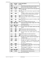
5.1.6 DMX Source
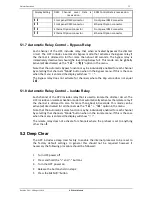
When the Ethernet module is fitted, the source of DMX and RDM can be assigned
between the existing 5 pin DMX connector and the optional Ethernet connector. It is
possible to select between the 4 possible combinations - refer to the following table.
The left digit indicates the source of level information while the right digit indicates the
source of RDM information.
Содержание HPC AIRGAP
Страница 1: ...HPC ...


