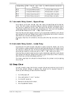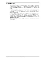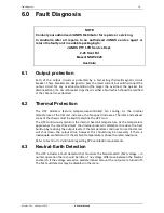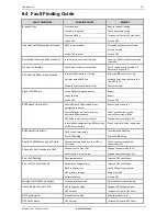
Equipment Description
5
Revision 2.0c – 30 August 2013
HPC User Manual
3.0 Equipment Description
3.1
Front Panel Layout
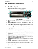
Refer to Figure 2 for a description of the front panel controls.
1.
Channel output sockets (rear panel):
The output sockets are located on the back
panel.
2.
Channel circuit breakers:
If a breaker trips during use ensure the fault has been
cleared before resetting.
3.
+
and
-
buttons:
These buttons select the DMX-512 start channel, are used to move
through menus and select functions and change values.
4.
EXIT and MENU/
buttons:
These buttons are used to navigate through the menus
and set DMX address.
5.
3-Digit Display:
Indicates currently selected DMX-512 start channel, the menu
position, and the various function options.
6.
SIGNAL LED:
Indicates the presence of DMX-512 signals.
7.
ERROR LED:
Flashes in the presence of a fault. In normal operation this LED should be
off.
8.
IC LED
: The Internal Control LED Illuminates when control is internal, ie. not from the
DMX-512 input.
9.
TERM LED:
Illuminates when the Terminate function is active.
10.
PHASE LEDs:
Three blue LEDs (one for each phase) indicate that the mains supply is
available. Note that all three LEDs should illuminate when power is available regardless
of the type of the mains supply used to power the HPC.
11.
DMX IN SOCKET:
Standard 5-pin AXR connector accepts DMX-512 signals from the
controller.
12.
DMX LOOP SOCKET:
Standard 5-pin AXR connector links the DMX-512 signals to other
dimmers or devices.
13.
Channel “Mode” Switch:
A switch per output channel is used to change the mode of
operation of that channel.
14.
Channel LED:
A multicolour LED per output channel is used to indicate the mode and
drive level of that channel.
6
3
4
5
1
2
2
1
(REAR)
4
3
Figure 2: HPC front panel layout
5
6, 7, 8, 9
10
11, 12
13
14
Содержание HPC AIRGAP
Страница 1: ...HPC ...

